Frequency compensation circuit applicable to high speed integrated amplifier

An integrated amplifier and frequency compensation technology, which is applied in the direction of improving the amplifier to reduce temperature/power supply voltage changes, etc., can solve the problems of integrated amplifier bandwidth expansion, CMOS circuit utility reduction, and frequency compensation weakening, so as to achieve easy layout matching and sensitivity The effect of reducing the speed and improving the stability

Inactive Publication Date: 2011-04-27
FUDAN UNIV
View PDF3 Cites 4 Cited by
  • Summary
  • Abstract
  • Description
  • Claims
  • Application Information

AI Technical Summary

Problems solved by technology

However, due to the continuous reduction of intrinsic gain, the effectiveness of this technology for CMOS circuits of deep submicron technology is reduced, and a load effect is generated at the output of the main stage amplifier. For low-power amplifiers, the frequency compensation effect is further weakened.
Therefore, it is a challenge to achieve bandwidth extension of integrated amplifiers while avoiding the use of on-chip inductors
Finally, CMOS integrated circuits are easily affected by power supply voltage, operating temperature, and process tolerances. Since frequency compensation circuits often use resonance or positive feedback, once the circuit parameters deviate, the circuit is easy to oscillate. Therefore, another problem that needs to be solved is How to keep the bandwidth of the integrated amplifier constant and improve its stability

Method used


Image

  • Frequency compensation circuit applicable to high speed integrated amplifier
  • Frequency compensation circuit applicable to high speed integrated amplifier
  • Frequency compensation circuit applicable to high speed integrated amplifier

Examples


Embodiment Construction

[0011] The present invention will be described in detail below with reference to the accompanying drawings.

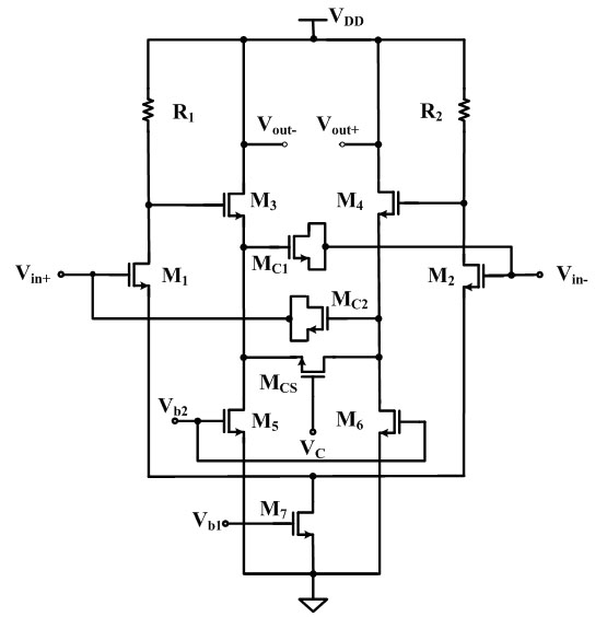
[0012] The present invention designs a frequency compensation circuit suitable for high-speed integrated amplifiers, and its basic application diagram is as follows figure 1 shown. The frequency compensation circuit is composed of a main stage amplifier and a frequency compensation circuit. Among them, the primary amplifier is a fully differential amplifier with a resistive load. The parasitic capacitance brought by the resistive load is smaller than that of the active load, which is suitable for high-frequency application circuits. The frequency compensation circuit consists of a source follower with variable gain and a pair of compensation capacitors. The input signal is applied to the main stage amplifier input MOS tube M 1 , M 2 at the gate terminal, the load resistor R at the drain terminal 1 , R 2 Generate a voltage signal output on. MOS tube M 3 ~M 6 C...


PUM


Abstract

The invention belongs to the technical field of integrated amplifiers, in particular relates to a frequency compensation circuit applicable to a high speed integrated amplifier. The frequency compensation circuit is composed of a gain variable source follower and a pair of compensation capacitors which are inserted between the inphase input terminal and output terminal of a fully differential primary amplifier loaded by a resistance. The circuit can utilize a controllable multiplying negative Miller capacitance to offset the positive Miller capacitance effect produced by a CMOS (complementary metal oxide semiconductor) transistor source drain parasitic capacitance Cgd, and a small load effect is produced to a primary circuit, thus obviously improving bandwidth. Meanwhile an external control voltage is used for regulating an equivalent negative Miller capacitance, thus eliminating frequency response overshoot probably produced by the circuit at different power supply voltages or different working temperatures and ensuring frequency band and operation of the circuit to be stable.

Description

technical field [0001] The invention belongs to the technical field of integrated amplifiers, and in particular relates to a frequency compensation circuit suitable for high-speed integrated amplifiers. technical background [0002] With the development of information technology, the processing speed of information data is required to be higher and higher, and integrated amplifier is one of the most basic units of various circuits. For example, the RF front-end in the communication system needs more and more high-speed variable gain amplifiers, and the detection amplifier is required to have the characteristics of ultra-wideband in the measuring instrument. However, the cutoff frequency f of the CMOS process T Due to limitations, the parasitic capacitance of the layout plays an increasingly negative role with the increase of the operating frequency. The traditional method of expanding the frequency band through negative feedback is at the expense of DC gain, and the applica...

Claims


Application Information

Patent Timeline
Patent Type & Authority Applications(China)
IPC IPC(8): H03F1/30
Inventor 黄杏丽秦希洪志良
Owner FUDAN UNIV
Why Eureka
Try Eureka