
Deblocking filter for video coder and implementation method thereof

A technology of deblocking filter and video encoder, applied in digital video signal modification, television, electrical components, etc., can solve the problems of transformation coefficient error, life cycle less than one year, visual discontinuity of image block boundary, etc., to achieve faster Design speed, good versatility, fast design effect

Active Publication Date: 2011-05-11
PEKING UNIV SHENZHEN GRADUATE SCHOOL
View PDF2 Cites 17 Cited by
  • Summary
  • Abstract
  • Description
  • Claims
  • Application Information

AI Technical Summary

Problems solved by technology

In particular, the current life cycle of electronic products is less than one year, how to design new electronic products as much as possible has become a problem for manufacturers to solve
There are two reasons for this: the most important reason is the discrete cosine transform (DCT) transformation based on the block-based intra-frame and inter-frame prediction residuals. The quantization process of the transform coefficients is relatively rough, so the transformation restored by the inverse quantization Coefficients are also biased, causing visual discontinuities on image patch boundaries
The second reason comes from block motion compensation prediction. In the case of multiple reference frames, the reference data required for motion compensation of different sub-blocks is selected from which reference frame to copy according to the residual energy, so that The reference data near the boundary of two adjacent sub-blocks may come from different reference frames
[0007] Therefore, the existing ASIC design method for deblocking filter still needs to be improved and improved

Method used


Image

  • Deblocking filter for video coder and implementation method thereof
  • Deblocking filter for video coder and implementation method thereof
  • Deblocking filter for video coder and implementation method thereof

Examples


Embodiment Construction

[0049] The present invention will be further described in detail below through specific embodiments in conjunction with the accompanying drawings.

[0050] 1. Overview of Video Encoder

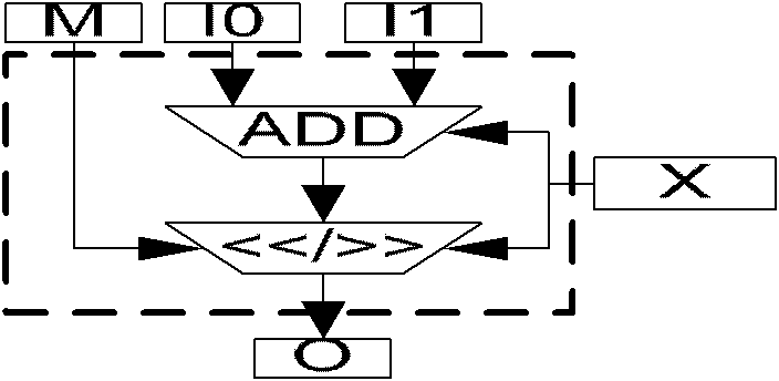
[0051] Video coding technology is a key technology for digital media storage and transmission, and it is widely used in digital TV, video communication, network streaming media and other fields. The invention relates to an implementation method of a deblocking filter based on the idea of ​​an operator, which is suitable for the deblocking filter of various image / video / audio DCT transformation data in the field of signal processing.

[0052] Currently in the field of video coding, the new digital video coding standard - H.264 jointly formulated by the Joint Video Team (JVT) jointly established by the International Telecommunications Union (ITU-T) and the International Organization for Standardization (ISO) has been widely used. The H.264 algorithm is not only H.264 of the International Telecom...


PUM


Abstract

The invention discloses a deblocking filter for a video coder and an implementation method thereof. The method comprises the following steps: mapping each filtering function of the deblocking filter of the video coder described by the high level program language algorithm into the hardware logic description formed by operator units; and generating a hardware integrated circuit of the deblocking filter by the hardware logic description formed by the operator units. By applying the invention, a system engineer can realize fast mapping from the deblocking filtering algorithm described by the high level language to a hardware circuit at the lower layer according to a complete operator cell library capable of supporting the description of the high level language algorithm, thereby finishing the fast design of the deblocking filter integrated circuit. Moreover, the deblocking filter and other application specific integrated circuit (ASIC) parts in the video coder can perform parallel flow operation, thereby increasing the design speed of the ASIC of the video coder. The deblocking filter can be suitable for different video coder structures and has good universality.

Description

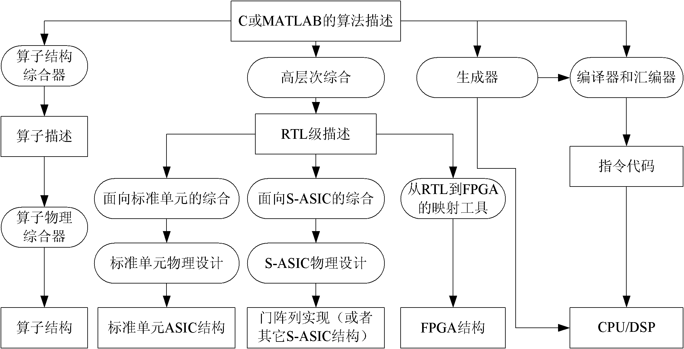
technical field [0001] The present invention relates to digital video processing technology, in particular, to a deblocking filter for a video encoder and its implementation method. Background technique [0002] Integrated circuit design methodology is a methodology used to guide integrated circuit design. The current integrated circuit design, especially the large-scale integrated circuit design, its common design process is: the system engineer proposes the system function framework according to the functional requirements, and the software engineer uses the computer advanced programming language (such as: Java, C, C++, Matlab, etc.) Describe the functional framework of the system to obtain the algorithm description of the high-level programming language of the integrated circuit; then the integrated circuit design engineer uses the hardware description language (such as: Verilog, VHDL, etc.) to synthesize the algorithm description into a netlist file, and then uses a spec...

Claims


Application Information

Patent Timeline
IPC IPC(8): H04N7/26H04N7/50H04N19/117H04N19/615H04N19/80
Inventor 昌锋王新安胡子一张兴
Owner PEKING UNIV SHENZHEN GRADUATE SCHOOL
Learn More