Method and device for photocatalytic reaction

A photocatalytic reaction and photocatalyst technology, applied in the field of photocatalytic reaction, can solve the problems of low light utilization rate and inability to effectively suppress the reverse reaction, and achieve the effect of improving the light utilization rate, increasing the scattering probability, and increasing the gas-liquid interface

Inactive Publication Date: 2011-05-25
INST OF PHYSICS - CHINESE ACAD OF SCI
View PDF2 Cites 32 Cited by
  • Summary
  • Abstract
  • Description
  • Claims
  • Application Information

AI Technical Summary

Problems solved by technology

[0005] Therefore, the purpose of the present invention is to overcome the problem that the photocatalytic reaction method of the prior art can not effectively suppress the reverse reaction and the light utilization rate is low, propose a kind of photocatalytic reaction method that effectively suppresses the reverse reaction and the light utilization rate is higher and be used in this method installation

Method used


Image

  • Method and device for photocatalytic reaction
  • Method and device for photocatalytic reaction
  • Method and device for photocatalytic reaction

Examples


Embodiment 1

[0037] This embodiment is used to illustrate the application of the photocatalytic reaction method and device of the present invention in the photocatalytic water splitting reaction.

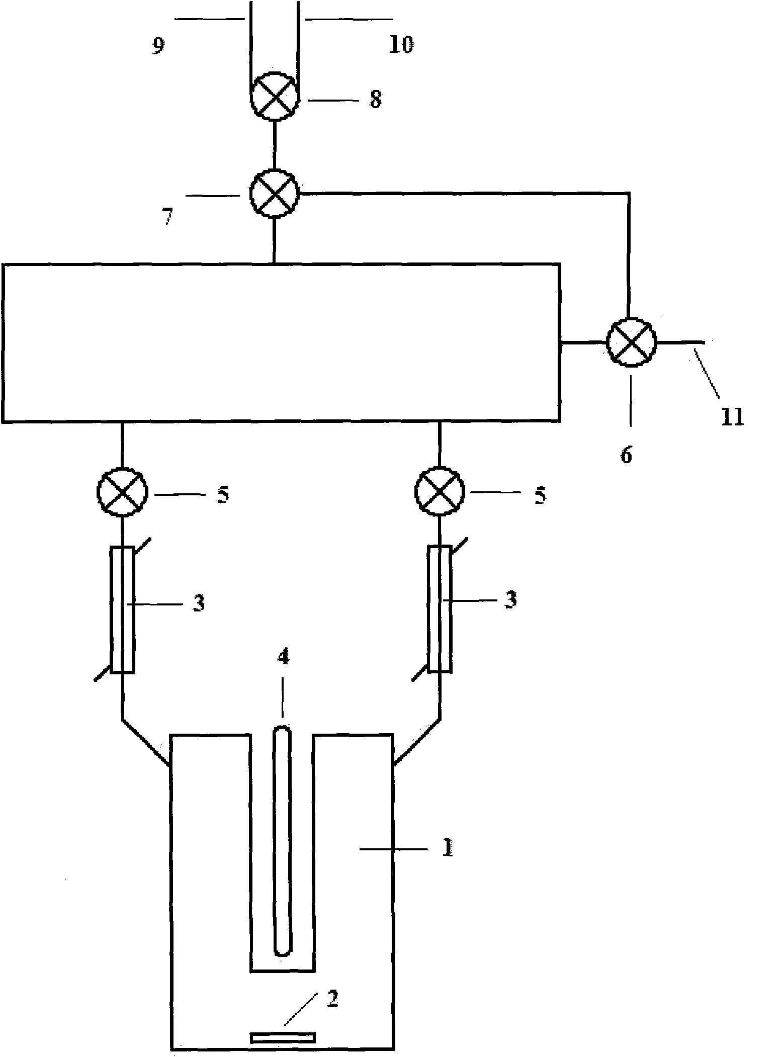
[0038] The device used in this example is figure 1 As shown, the device includes 1 reaction vessel, 2 ultrasonic nebulizers, 3 condenser sleeves, 4 light sources, 5-7 three-way valves, 8 four-way valves, 9-10 gas chromatography interfaces, 11 vacuum pump interfaces (5 -10 collectively referred to as the "sampling section"). Among them, the two adjacent branches of the four-way valve 8 are connected, and form a quantitative sampling loop with the glass tube between the three-way valve 7, and the other two adjacent branches of the four-way valve 8 are connected through the gas chromatography interface 9 and 10 are connected to a gas chromatograph. Turning the four-way valve 8 can connect or disconnect the quantitative sampling loop with the chromatogram. When it is in the disconnected state, op...

Embodiment 2

[0055] This embodiment is used to illustrate the application of the photocatalytic reaction method and device of the present invention in the photocatalytic degradation of organic pollutants.

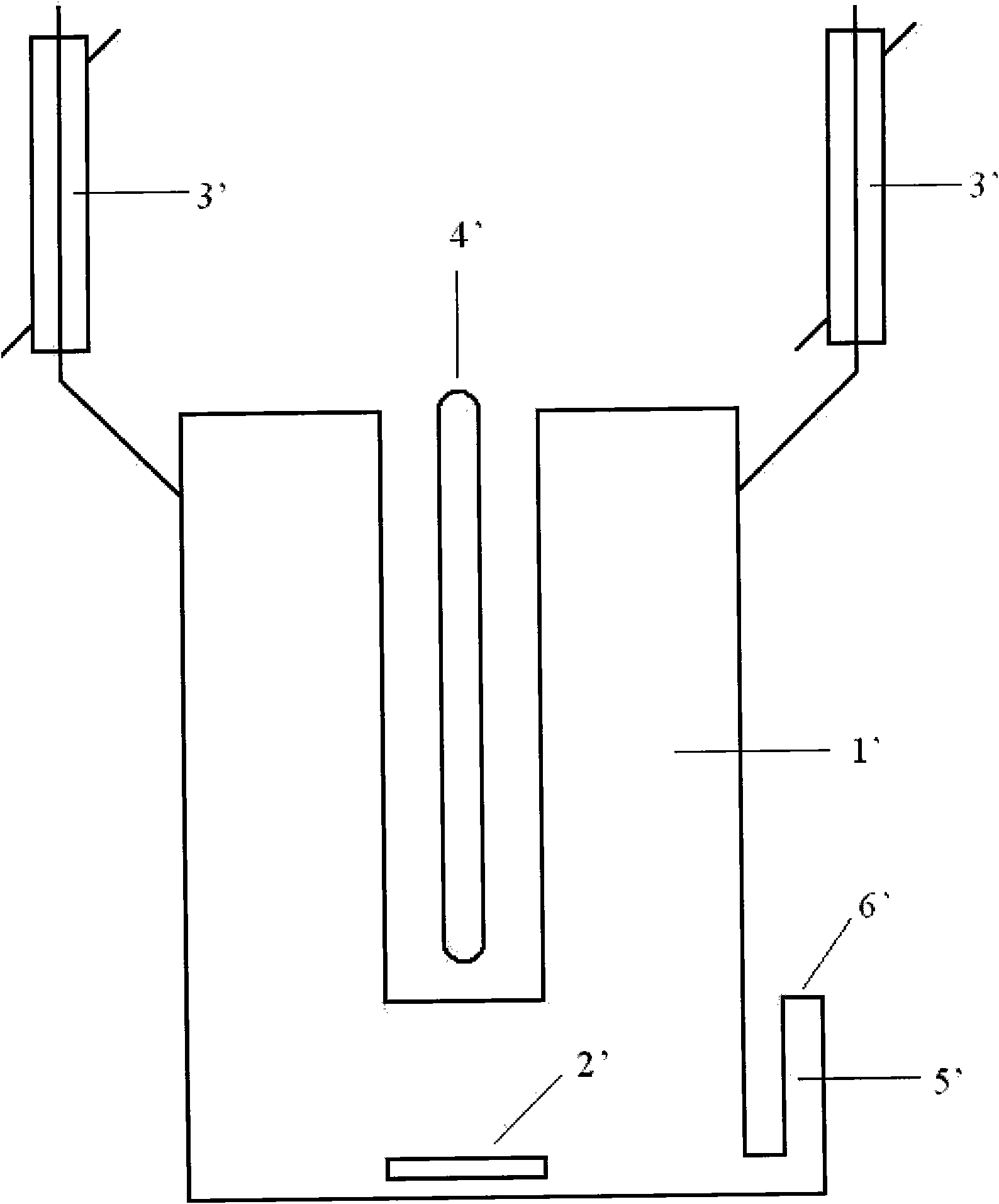
[0056] The device used in this example is figure 2 As shown, the device includes 1' reaction vessel, 2' ultrasonic nebulizer, 3' condensation sleeve, 4' light source, 5' sampling part and 6' sampling part cover. Among them, the reaction vessel 1' is connected to the atmosphere through the condensation sleeve 3' to supplement the oxygen needed in the reaction process; a sampling part cover 6' is added to the sampling part 5' to prevent the escape of atomized droplets . Wherein the reaction vessel 1' is a quartz glass material.

[0057] The specific operation steps are as follows:

[0058] 1) 25mg TiO 2 and 50ml 2×10 -5 m / l rhodamine B solution was added to figure 2 In the shown reaction vessel 1 ';

[0059] 2) Install the 150W mercury lamp on figure 2 In the position of the power...

Embodiment 3

[0071] This embodiment is used to illustrate the application of the photocatalytic reaction method and device of the present invention in the photocatalytic water splitting reaction.

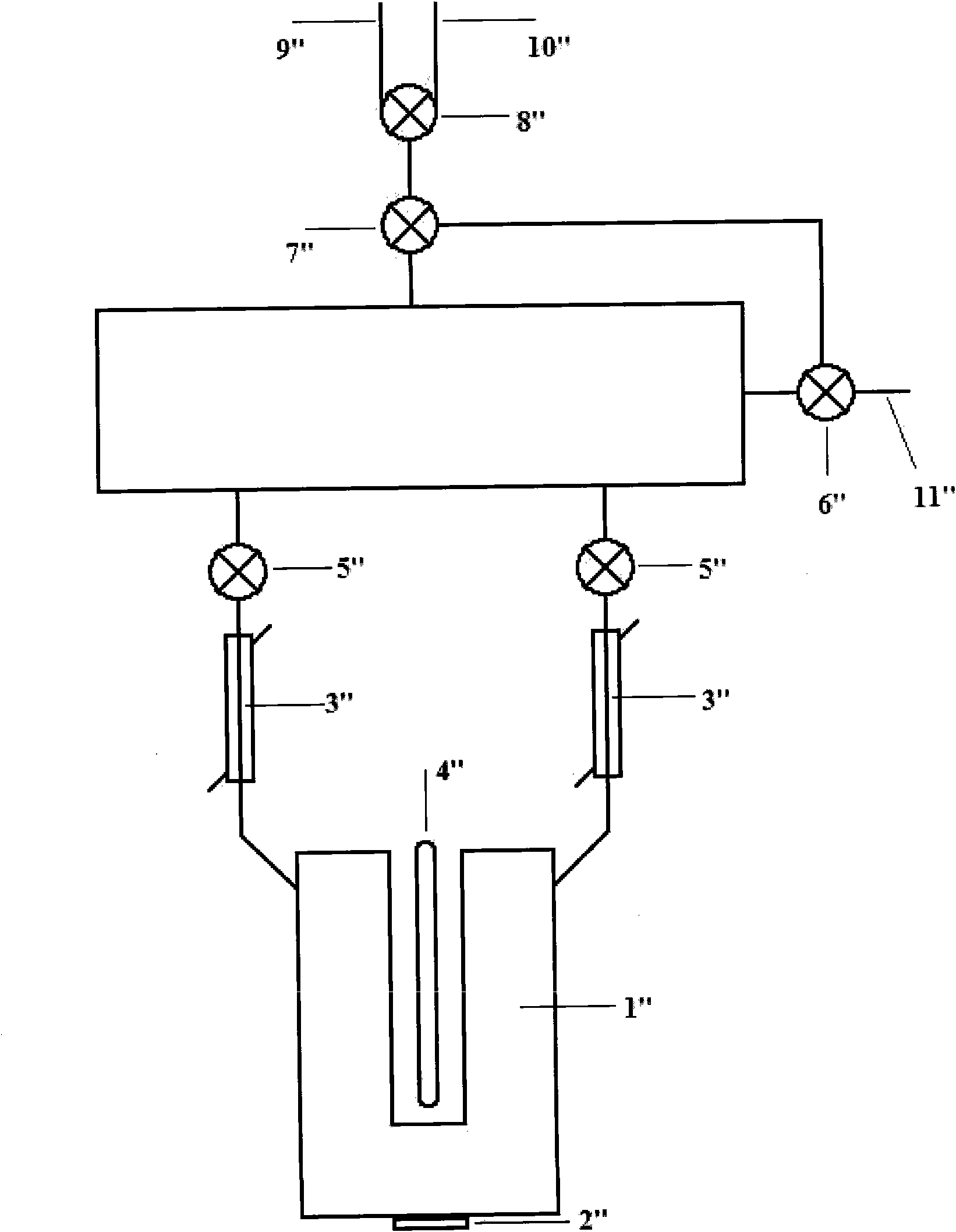
[0072] The device used in this example is image 3 As shown, the device includes 1" reaction vessel, 2" ultrasonic nebulizer, 3" condensation sleeve, 4" light source, 5"-7" three-way valve, 8" four-way valve, 9"-10" gas chromatograph Interface, 11" vacuum pump interface (5"-10" can be collectively referred to as "sampling part"). Among them, the ultrasonic atomizer 2" is in contact with the outer bottom surface of the reaction vessel 1"; the two adjacent branches of the four-way valve 8" are connected, and form a quantitative sampling loop with the glass tube between the three-way valve 7". , the other two adjacent branches of the four-way valve 8" are connected to the gas chromatograph through 9" and 10". Turning the four-way valve 8" can make the quantitative sampling loop connected or discon...


PUM


Abstract

The invention provides a photocatalytic reaction method, comprising the steps of: atomizing a solution or suspension containing a photocatalyst and a reactant to form mist; and leading the mist to be subjected to photocatalytic reaction by utilizing a light source. The invention also provides a photocatalytic reaction device, which comprises a reaction vessel, an atomizer arranged inside or outside the reaction vessel, a condensation sleeve communicated with the reaction vessel, and the light source used for photocatalytic reaction. By means of the method and the device, a gas-liquid interface is enlarged by changing the form of water, i.e. atomizing the liquid-phase solution of the catalyst, so as to reduce the escape path of hydrogen gas and effectively inhibit the occurrence of reverse reaction, meanwhile, because the scattering probability of light in the mist is increased and the effective absorption is enhanced, the light utilization rate and the catalytic efficiency of the photocatalyst are greatly improved.

Description

technical field [0001] The present invention relates to a method and device for photocatalytic reaction, more specifically, to a method and device for photocatalytic decomposition of water to produce hydrogen and photocatalytic degradation of organic pollutants. Background technique [0002] Energy and environmental issues are two important issues that human society must solve to achieve sustainable development. At present, with the depletion of fossil energy and the seriousness of environmental problems, it is imminent to find clean and pollution-free renewable new energy and the degradation and emission reduction of pollutants. [0003] Among many new energy sources, solar energy has attracted widespread attention due to its inexhaustible absolute advantage. In solar energy utilization technology, photocatalytic water splitting to produce hydrogen and photocatalytic degradation of organic pollutants are of great significance. Hydrogen energy is a clean, efficient, safe, ...

Claims


Application Information

Patent Timeline
Patent Type & Authority Applications(China)
IPC IPC(8): B01J19/12
Inventor 孟庆波范玉尊黄小铭陈国萍李冬梅罗艳红
Owner INST OF PHYSICS - CHINESE ACAD OF SCI
Why Eureka
Try Eureka