Method for multi-effect evaporation and dehydration of solid material

A solid material, multi-effect evaporation technology, applied in the direction of multi-effect evaporation, drying of solid materials, solid fuel, etc., can solve the problems of complicated installation, high consumption of raw steam, and complicated installation.

Inactive Publication Date: 2011-05-25
GOUDEN KOLEN CO LTD
View PDF8 Cites 6 Cited by
  • Summary
  • Abstract
  • Description
  • Claims
  • Application Information

AI Technical Summary

Problems solved by technology

The cooking device disclosed in the patent CN1989227A has a complex structure, especially wherein the equipment for separating gas, liquid and solid from each other is carried out by a separate liquid separator, which includes a porous rotary table or a porous cone inside the device and The porous tube and the separation table at the bottom of the device, in which only the porous tube plays the role of liquid-solid separation, while the porous rotary table and the separation table seriously occupy the internal space of the device, and the patent requires that the porous rotary table and the separation table can be rotated , it is also necessary to equip the corresponding power equipment and transmission equipment in the device, and make these power equipment and transmission equipment able to withstand the high temperature and high pressure in the device, which further complicates the device
In addition, in this patent, the porous pipe only plays the role of drainage, and the entry and exit of steam depends on the arrangement of multiple steam inlets and steam outlets along the height direction of the device, which also complicates the device
And this patented method does not use the flash steam and hot water produced in cooking to preheat the raw materials, so the raw steam (heat energy) consumption is high (about 2-3 times that of this patented technology)
In addition, the K-fuel technology digester is equipped with upper and lower lock hoppers for continuous cooking and intermittent material feeding (discharging). The material containing lignite passes through the lock valve under differential pressure, and the solid matter in the material will wear the valve greatly; Before the lower lock hopper is discharged, it is difficult to drain the free water first, which will have a negative impact on the quality improvement efficiency
[0006] However, the D-K non-evaporative dehydration technology can only realize semi-continuous operation at present, which affects the production capacity and operation stability of the device, and the water content of the lignite after cooking is still high, which needs to be further reduced

Method used


Image

  • Method for multi-effect evaporation and dehydration of solid material
  • Method for multi-effect evaporation and dehydration of solid material
  • Method for multi-effect evaporation and dehydration of solid material

Examples


Embodiment 1

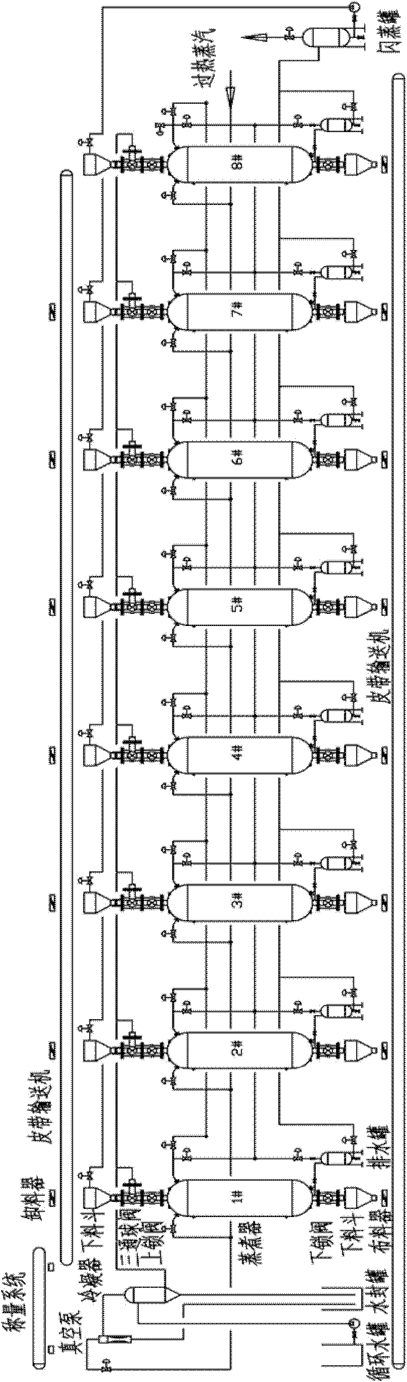
[0045] The steps for each digester are as follows figure 1 As shown, 8 digesters are provided, numbered 1-8 respectively, and the water-containing lignite passes through the weighing system, unloader and belt conveyor in sequence, from the lower hopper at the top of each digester, the three-way ball valve and the lock valve Enter these 8 digesters respectively, and each digester repeatedly executes the steps i-viii described in this article according to the order of time, and at any moment, the operations performed by each digester are as follows: digester 1 carries out In step i, the digester 2 performs step ii, ... and so on..., the digester 8 performs step viii without vacuumizing. Wherein, the saturated steam discharged from the digester 5 is used as the saturated steam of the digester 4, and the third steam discharged from the digester 6 is used as the second steam in the digester 3 until equal pressure is reached between the two digesters. The fourth steam discharged fr...

Embodiment 2

[0050] The layout of each boiler is according to figure 1As shown, but nine digesters are provided, numbered 1-9 respectively, and the lignite containing water enters these nine digesters respectively, and each digester is repeatedly performing steps i-ix described herein according to the sequence of time, And at any given moment, the operations performed by each digester are as follows: digester 1 performs step i, digester 2 performs step ii, ... and so on ..., digester 8 performs step viii, digester 9 performs step iv. Wherein, the saturated steam discharged from the digester 5 is used as the saturated steam of the digester 4, and the third steam discharged from the digester 6 is used as the second steam in the digester 3 until equal pressure is reached between the two digesters. The fourth steam discharged from the digester 7 is used as the first steam in the digester 2 until pressure equalization is achieved between the two digesters. Wherein step vi is carried out for 2...

Embodiment 3

[0054] The layout of each boiler is according to figure 1 As shown, but nine digesters are provided, numbered 1-9 respectively, and the lignite containing water enters these nine digesters respectively, and each digester is repeatedly performing steps i-ix described herein according to the sequence of time, And at any given moment, the operations performed by each digester are as follows: digester 1 performs step i, digester 2 performs step ii, ... and so on ..., digester 8 performs step viii, digester 9 performs step iv. Wherein, the saturated steam discharged from the digester 5 is used as the saturated steam of the digester 4, and the third steam discharged from the digester 6 is used as the second steam in the digester 3 until equal pressure is reached between the two digesters. The fourth steam discharged from the digester 7 is used as the first steam in the digester 2 until pressure equalization is achieved between the two digesters. Wherein step vi is carried out for ...


PUM


Abstract

The present invention provides a method for multi-effect evaporation and dehydration of a solid material, which comprises preparation of a plurality of digesters. The digesters are connected in parallel relative to the flow direction of the solid material, and each digester can repeatedly heat, evaporate and dehydrate the solid material step by step from a low temperature to a high temperature according to a time sequence. In the preferential embodiment, at least part of the digesters needs vacuum pumping prior to final discharge.

Description

field of invention [0001] The present invention relates to a method of dewatering solid materials. Background technique [0002] Lignite is a kind of coal with a low degree of coalification. It has a high water content and is easily weathered in the air. It contains a certain amount of primary humic acid, and its volatile content is generally between 45-55%. Due to the high moisture content and low calorific value of lignite, it is easy to weather and spontaneously combust, and the transportation cost per unit energy is high, which is not conducive to long-distance transportation and storage. The thermal efficiency of direct combustion of lignite is also very low. Lignite as a raw material needs to reduce the moisture in the coal to less than 10% in the process of liquefaction, dry distillation and gasification. Therefore, lignite upgrading and processing is called the key to the efficient development and utilization of lignite. The so-called upgrading of lignite means th...

Claims


Application Information

Patent Timeline
Patent Type & Authority Applications(China)
IPC IPC(8): F26B3/00F26B23/00F26B25/00
CPCB01D1/26C10L5/04C10L9/08C10L2290/06C10L2290/148C10L2290/146C10L2290/08C10L2290/46C10F5/00F26B3/06F26B2210/00
Inventor 徐斌褚腊林马红松
Owner GOUDEN KOLEN CO LTD
Why Eureka
Try Eureka