Lithium ion battery system for hybrid electric vehicle (HEV)

A hybrid electric vehicle and lithium-ion battery technology, applied in the field of heat dissipation system design, can solve the problems of narrow adaptable temperature range, few applications, high cost, etc., to overcome the large space of serial heat dissipation mode and parallel heat dissipation structure, and ensure temperature uniformity , The effect of simple manufacturing process

Active Publication Date: 2011-05-25
CHONGQING CHANGAN AUTOMOBILE CO LTD +1
View PDF4 Cites 24 Cited by
  • Summary
  • Abstract
  • Description
  • Claims
  • Application Information

AI Technical Summary

Problems solved by technology

According to the cooling medium, it can be divided into: water cooling and air cooling; among them, water cooling uses water or ethanol as the cooling medium, which has the advantages of being insensitive to position and adapting to a wide temperature range, but has the disadvantages of complex structure, high cost, and complicated maintenance. There are few applications; although the air cooling method has disadvantages such as low efficiency and narrow temperature range, it will be greatly improved when combined with the vehicle air conditioning system. In addition, it has the advantages of simple design, low cost, and easy implementation. Currently applied mainstream
The air cooling system of the battery is divided into two types: series connection and parallel connection. Although the series connection has the characteristics of simplicity and low cost, it has the disadvantage of large temperature difference of the battery pack. The parallel heat dissipation system is limited by the layout space of the vehicle, and the cooling efficiency is low.

Method used


Image

  • Lithium ion battery system for hybrid electric vehicle (HEV)
  • Lithium ion battery system for hybrid electric vehicle (HEV)

Examples


specific Embodiment approach

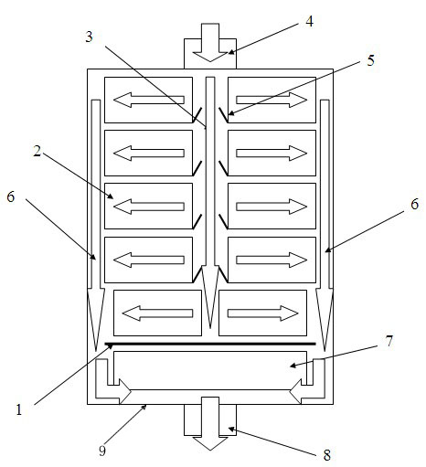
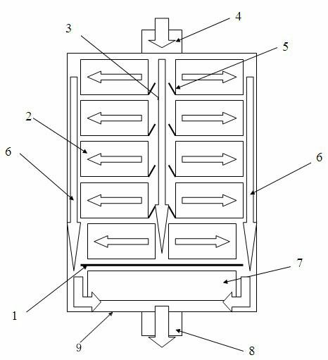
[0012] The lithium-ion battery system proposed by the present invention can be used for plug-in hybrid vehicles, see figure 1 , which includes: 1. windshield; 2. battery module group; 3. air inlet wedge-shaped channel; 4. battery box air inlet; 5. diversion grille; 6. air outlet channel; 7. battery management System and high voltage device part; 8. Battery box air outlet; 9 Battery box. The battery box 9 is fixed under the chassis of the vehicle by bolts. The battery box air inlet 4 is designed at one end of the battery box near the front cabin of the vehicle, and the battery box air outlet 8 is designed at the other end of the battery box near the trunk. A total of 10 groups of battery module groups 2 are symmetrically arranged in two rows in a single layer and arranged in the battery box 9, and a wedge-shaped air inlet channel 3 is formed between the two rows, which is formed by reducing the gap between the symmetrical arrangement of the batteries on both sides. The inner d...


PUM


Abstract

The invention provides a lithium ion battery system for a hybrid electric vehicle (HEV), comprising a battery box body, battery module groups in the battery box body, a battery management system and a high-voltage device, wherein the battery management system is arranged in the battery box body and is close to one end of a forward engine room in the HEV; the battery box body is provided with an air inlet and an air outlet; the battery module groups are symmetrically arranged at the left and the right in two rows along an air-in/air-out direction; an air-in wedge-shaped channel is reserved between the two rows of the battery module groups; an air-out channel is reserved between the outside of the left and the right battery module groups and the battery box body; the air-out channel is communicated with the air outlet of the battery box body; and a diffuser grid plate is arranged in the air-in wedge-shaped channel so as to strengthen wind resistance to evenly disperse the air at the two sides of a battery pack. Air channels are arranged in a gap between the battery module groups, thus solving the problems of long air flow, unconspicuous cooling effect, and larger temperature difference between the air inlet and the air outlet, and ensuring that the single battery inside the battery pack is even in temperature, simple in structure, and easy to manufacture.

Description

technical field [0001] The invention belongs to the technical field of automotive electronics applications, and in particular relates to the design of a cooling system for a battery pack used in a plug-in hybrid electric vehicle. Background technique [0002] The power battery is the core component of a hybrid electric vehicle, and its superior performance directly affects the performance of the vehicle. Lithium-ion batteries are emerging batteries in the 1990s. They have the advantages of small size, high specific energy and specific power, high voltage, long life, and environmental protection and pollution-free. However, lithium-ion batteries are sensitive to temperature, and they exhibit different charge-discharge curve characteristics (capacity, internal resistance, power, etc.) at different temperatures. The difference in temperature in the same battery pack is the main reason for the poor consistency of the battery, and After the batteries are grouped, the overall lif...

Claims


Application Information

Patent Timeline
Patent Type & Authority Applications(China)
IPC IPC(8): H01M10/42H01M10/50H01M10/0525H01M2/10B60K11/06H01M10/613H01M10/625H01M10/6554H01M10/6566
CPCY02E60/12Y02T10/7011Y02E60/122Y02E60/10
Inventor 杨培蕾岳刚袁昌荣任勇苏岭
Owner CHONGQING CHANGAN AUTOMOBILE CO LTD
Why Eureka
Try Eureka