Flyback converter leakage inductance absorption and soft switching control

A technology of flyback converter and flyback transformer, which is applied in the direction of control/regulation system, conversion equipment with intermediate conversion to AC, conversion of DC power input to DC power output, etc. Increased system operating frequency, large switching losses, etc.

Inactive Publication Date: 2011-05-25
上海岩芯电子科技有限公司
View PDF1 Cites 15 Cited by
  • Summary
  • Abstract
  • Description
  • Claims
  • Application Information

AI Technical Summary

Problems solved by technology

[0003] The soft switching technology of the flyback converter can be roughly divided into two types: resonant technology and active clamp technology. figure 2 The quasi-resonant technology shown uses parasitic devices to make the current or voltage in the converter change according to the quasi-sinusoidal law, and realizes the zero-voltage or zero-current switching of the switching device. It has the advantages of simple circuit structure and no need to add additional devices, but the quasi-resonant technology only It realizes the soft switching of power devices, and does not absorb and utilize the leakage inductance that affects the efficiency of the flyback converter. On the other hand, under light load conditions, the quasi-resonant control will greatly increase the system operating frequency, causing larger switching losses, thereby offsetting the losses reduced by soft-switching techniques, so quasi-resonant techniques are not ideal at light loads
like image 3 The shown active clamping technology realizes the absorption of leakage inductance and soft switching action at the same time. The active clamping technology controls the turn-off time of the auxiliary switch tube and turns on the power device during the freewheeling period of the anti-parallel diode to achieve zero voltage turn-on. Therefore, in order to ensure soft switching action, the power devices must be turned on in the negative half cycle of the C1 and Lk resonant currents, which will inevitably limit the range of duty cycle changes. Active clamping technology is more suitable for switching power supplies where the duty cycle does not vary greatly. In some occasions, like the duty cycle of the flyback transformer in the AC module is modulated by a sine wave, the active clamp technology cannot achieve soft switching action in the entire range

Method used


Image

  • Flyback converter leakage inductance absorption and soft switching control
  • Flyback converter leakage inductance absorption and soft switching control
  • Flyback converter leakage inductance absorption and soft switching control

Examples


Embodiment Construction

[0016] Preferred embodiments of the present invention are described in detail as follows in conjunction with accompanying drawings:

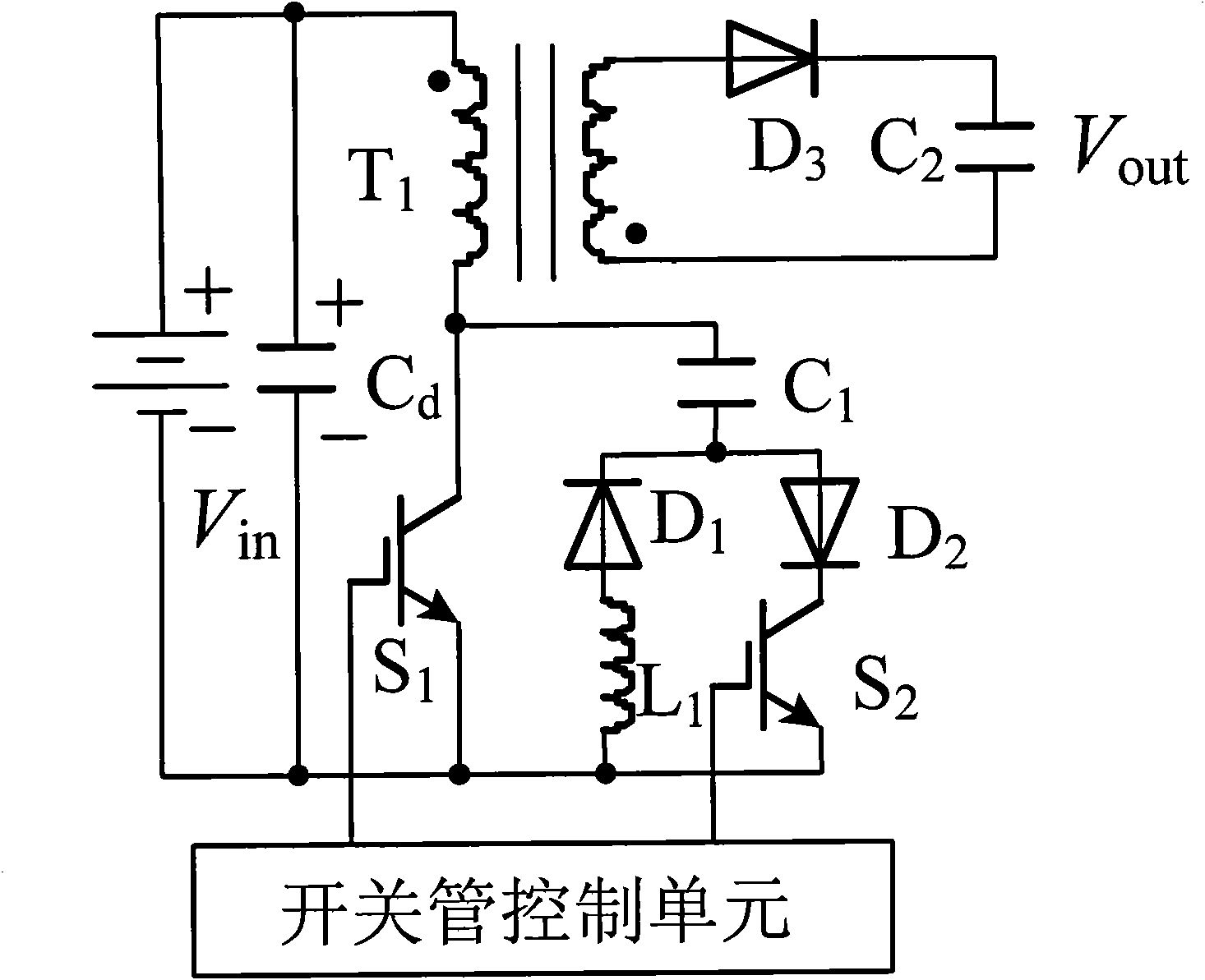
[0017] The leakage inductance absorbing circuit of the flyback converter is composed of a flyback converter and a leakage inductance absorbing circuit, and the flyback converter includes a flyback transformer T 1 , switch tube S 1 , Diode D 3 and filter capacitor C 2 , flyback transformer T 1 The same-named terminal of the primary side is connected to the positive terminal of the input power supply, and the non-identical terminal of the primary side is connected to the switch tube S 1 Drain, switch tube S 1 The source is connected to the negative terminal of the power supply, and the flyback transformer T 1 The non-identical end of the secondary side is connected to the diode D 3 Anode, the terminal with the same name on the secondary side is connected to the filter capacitor C 2 One end of the diode D 3 The cathode is connected to the f...


PUM


Abstract

The invention discloses a flyback converter leakage inductance absorption circuit and a control method thereof. Leakage inductance energy is absorbed by using an energy storage capacitor at the moment that a power device is cut off and controlled through a resonance inductor and an auxiliary switching device, the leakage inductance energy is fed back to an input power supply, and meanwhile, soft switching operations of all switching devices are realized. The circuit can realize absorption of leakage inductance and soft switching operations of the switching devices, effectively improves the efficiency of a system, is not affected by the duty ratio, and is particularly suitable for the occasions of micro inverters in alternative control (AC) modules and the like.

Description

Technical field: [0001] The invention relates to a flyback converter in an electric energy conversion device, in particular to a flyback converter leakage inductance absorption and soft switching control. Background technique: [0002] Miniaturization is the goal pursued by current power conversion device products. Increasing the switching frequency can reduce the volume of components such as inductors and capacitors, but the increase in switching frequency will increase the switching loss. Therefore, soft switching designed to reduce switching loss Technology came into being. The flyback converter has the advantages of simple circuit and high reliability. It is widely used in low-power power supplies and low-power inverters. It is especially suitable as a typical circuit for AC modules in photovoltaic grid-connected systems. The concept of AC modules is It has been proposed in recent years. In this AC module system, each group of photovoltaic modules is equipped with a mic...

Claims


Application Information

Patent Timeline
Patent Type & Authority Applications(China)
IPC IPC(8): H02M3/28H02M3/335
CPCY02B70/1491Y02B70/10
Inventor 吴春华杨宇徐坤
Owner 上海岩芯电子科技有限公司
Why Eureka
Try Eureka