Coal-fired power generation and waste heat power generation coupling system for private station of cement kiln

A waste heat power generation and power generation system technology, applied in cement production, waste heat treatment, mechanical equipment, etc., can solve problems such as increased operational difficulty, increased initial investment, and complex structure of single-pressure steam turbines, and achieves improved thermoelectric conversion efficiency and reduced coal consumption. The effect of less quantity and saving one-time investment

Active Publication Date: 2011-06-01
NANJING KESEN KENEN ENVIRONMENT & ENERGY
View PDF6 Cites 24 Cited by
  • Summary
  • Abstract
  • Description
  • Claims
  • Application Information

AI Technical Summary

Problems solved by technology

However, at present, the waste heat turbines using the dual-pressure system generally adopt the supplementary steam turbine, that is, the steam generated by the low-pressure steam drum is used as th

Method used


Image

  • Coal-fired power generation and waste heat power generation coupling system for private station of cement kiln
  • Coal-fired power generation and waste heat power generation coupling system for private station of cement kiln
  • Coal-fired power generation and waste heat power generation coupling system for private station of cement kiln

Examples


Embodiment 1

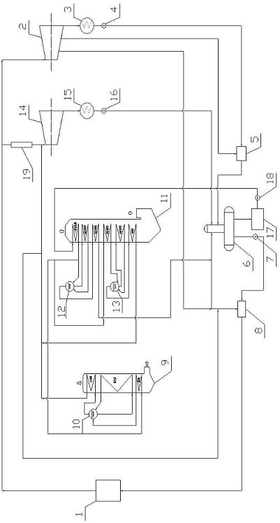
[0017] The structure of this embodiment is as figure 1 As shown, a coupling system for coal-fired power generation and waste heat power generation in a cement kiln self-contained power station includes a coal-fired boiler 1, a coal-fired power generation condensing steam turbine 2, a condenser 3, a condensate pump 4, a low-pressure heater 5, and an oxygen removal 6. Electric feed water pump 7. High pressure heater 8. Waste heat boiler at kiln tail 9. Steam drum at kiln tail 10. Waste heat boiler at kiln head 11. Low pressure steam drum at kiln head 12. Steam drum at kiln head 13. Waste heat turbine 14. Waste heat power generation Condenser 15, waste heat power generation condensate pump 16, intermediate water tank 17, feed water pump 18, temperature and pressure reducer 19.

[0018] The following procedures are described below:

[0019] (1) The working process of cement kiln waste gas waste heat: the cold air exchanges heat with clinker in the grate cooler of the cement kiln ...

Embodiment 2

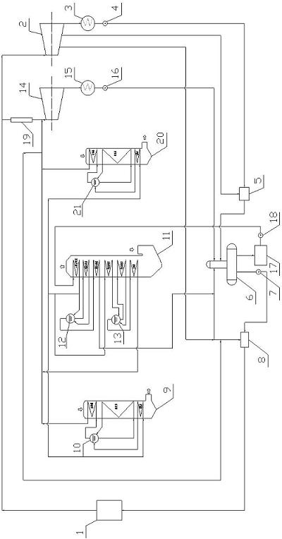
[0024] The structure of this embodiment is as figure 2 As shown, it is described in the following steps:

[0025] (1) The working process of the exhaust gas is as follows: a bypass air pipe is introduced at the end of the cement kiln, and the air volume accounts for about 15% of the total air volume. After heat exchange, the working medium in the waste heat boiler 20 is recycled to equipment such as cement kiln raw material mill and coal mill for further utilization.

[0026] (2) The working process of the circulating working fluid: the circulating working medium is pressurized by the intermediate water tank 17 and then by the feed water pump 18. After the pressurization, there are two water supply channels, and the other is the first-level economizer leading to the waste heat boiler 11 at the kiln head. The other road leads to the economizer of the waste heat boiler 20 at the kiln tail, and generates superheated steam after exchanging heat with the hot air drawn from the by...


PUM


Abstract

The invention discloses a coal-fired power generation and waste heat power generation coupling system for a private station of a cement kiln, comprising a coal-fired boiler, a kiln head waste heat boiler, a kiln tail waste heat boiler, a kiln head steam pocket, a kiln tail steam pocket, a condensing steam turbine, a condensate pump, a heater, a deaerator, a water feeding pump and related auxiliary devices, wherein the kiln head waste heat boiler utilizes a dual-pressure system; a primary economizer of the low-pressure system is used as a public economizer for the waste heat power generation; the high-pressure steam and the steam generated by the kiln tail waste heat boiler are collected to the main steam pipeline of the waste heat power generation system; one path of the main steam pipeline is connected with a steam turbine of the waste heat power generation system while the other path thereof is connected with non-adjustable extraction steam of a coal-fired steam turbine; one path ofthe main steam pipeline of the coal-fired unit is connected with the coal-fired steam turbine while the other path thereof is connected with the waste heat steam turbine. In the invention, the coal-fired power generation is rationally coupled with waste heat power generation system so that the problem that the stability of the waste heat power generation system of the cement kiln is low is solved, and the whole thermal circulating efficiency of the private station can be largely increased.

Description

technical field [0001] The invention relates to a coupling system of coal-fired power generation and waste heat power generation in a self-provided power station, and is particularly suitable for a system that needs to build a self-provided power station and simultaneously needs to recover waste heat from the kiln head and kiln tail of a cement kiln for power generation. Background technique [0002] Cement kiln waste heat power generation systems mainly include single-pressure, double-pressure, and flash systems. The heat recovery efficiency is different. After practical operation and calculation comparison, the power generation of the double-pressure system is about 1.5% to 1.9% higher than that of the single-pressure system. , the thermal efficiency of the unit increases by about 1.7%. That is, the heat recovery rate of the dual-pressure system is higher, so more dual-pressure systems are used. [0003] For the flash system, compared with the single-pressure system, the ...

Claims


Application Information

Patent Timeline
IPC IPC(8): F01K27/02F01K11/02F01D15/10F27D17/00
CPCY02P10/25Y02P40/121Y02P80/15
Inventor 侯宾才宋纪元谢奕敏杨宏宜王暐方明
Owner NANJING KESEN KENEN ENVIRONMENT & ENERGY
Why Eureka
Try Eureka