Composite dielectric protective film of plasma display panel (PDP) and preparation method thereof

A composite medium and display panel technology, used in tube/light screen manufacturing, solid cathode components, discharge tubes, etc., can solve problems such as inability to take into account simultaneously, unstable oxides, process difficulties, etc., to improve service life, reduce Production cost, effect of reducing discharge delay

Inactive Publication Date: 2011-06-08
SICHUAN COC DISPLAY DEVICES
View PDF3 Cites 10 Cited by
  • Summary
  • Abstract
  • Description
  • Claims
  • Application Information

AI Technical Summary

Problems solved by technology

The researchers found that this can indeed reduce the ignition voltage of PDP, but the problem is that this kind of oxide is extremely unstable and difficult to store in the atmosphere or in a solvent carrier, which brings great p

Method used


Image

  • Composite dielectric protective film of plasma display panel (PDP) and preparation method thereof
  • Composite dielectric protective film of plasma display panel (PDP) and preparation method thereof
  • Composite dielectric protective film of plasma display panel (PDP) and preparation method thereof

Examples


Embodiment 1

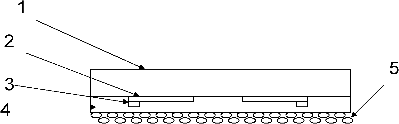
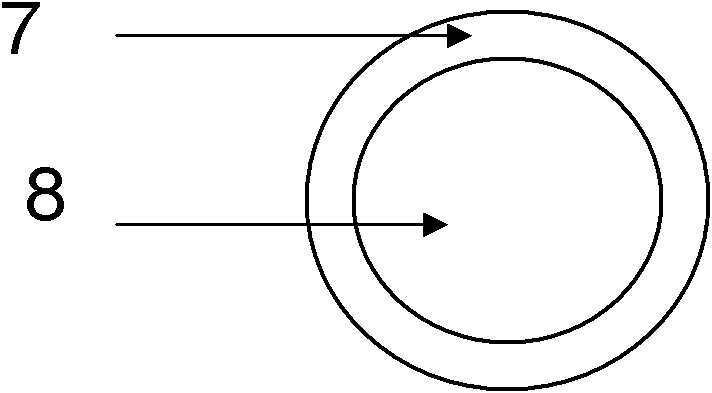
[0048] Select CaO particles with an average particle size of 1-2 μm and place them in the crucible of a thermal evaporation furnace. The crucible is equipped with a stirring device. The evaporation furnace uses Mg as the evaporation source. O 2 As a carrier gas, thermal evaporation coating is carried out, and when MgO with a thickness of 50nm is formed on the surface of CaO, the coating is stopped, and crystal particles with a core-shell structure are prepared.

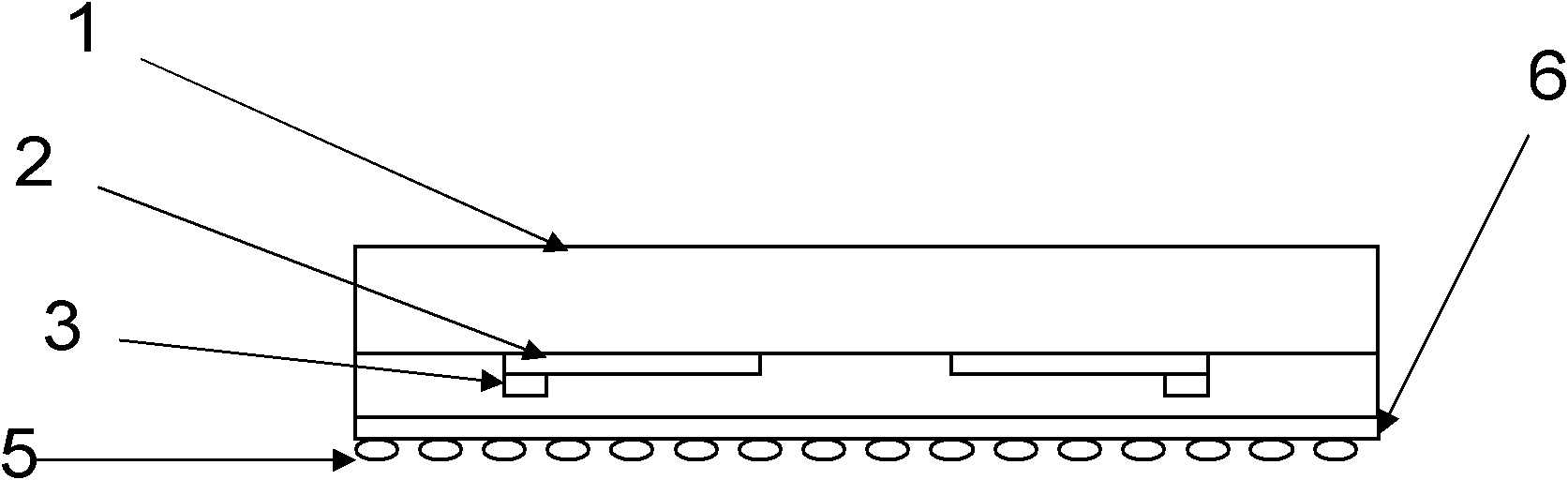
[0049] Put the crystal particles in the carrier solvent cellulose ether, and form a uniformly dispersed slurry after being punctured. Use a coating machine to evenly disperse the slurry on the surface of the medium layer. After drying at 150°C for 30 minutes, place it in a sintered In the furnace, it is sintered at 550°C to form a transparent composite dielectric protective film.

Embodiment 2

[0051] Select SrO particles with an average particle size of 1-2 μm and place them in the crucible of a thermal evaporation furnace. The crucible is equipped with a stirring device. The evaporation furnace uses Mg as the evaporation source. O 2 As the carrier gas, thermal evaporation coating is carried out, and when MgO with a thickness of 50nm is formed on the surface of SrO, the coating is stopped, and crystal particles with a core-shell structure are prepared.

[0052] Put the crystal particles in the carrier solvent cellulose ether, and form a uniformly dispersed slurry after being punctured. Use a coating machine to evenly disperse the slurry on the surface of the medium layer. After drying at 150°C for 30 minutes, place it in a sintered In the furnace, it is sintered at 550°C to form a transparent composite dielectric protective film.

Embodiment 3

[0054] Select ZnO particles with an average particle size of 1-2 μm and place them in the crucible of a thermal evaporation furnace. The crucible is equipped with a stirring device. The evaporation furnace uses Mg as the evaporation source. O 2 As the carrier gas, thermal evaporation coating is carried out, and when MgO with a thickness of 50nm is formed on the surface of ZnO, the coating is stopped, and crystal particles with a core-shell structure are prepared.

[0055] Put the crystal particles in the carrier solvent cellulose ether, and form a uniformly dispersed slurry after being punctured. Use a coating machine to evenly disperse the slurry on the surface of the medium layer. After drying at 150°C for 30 minutes, place it in a sintered In the furnace, it is sintered at 550°C to form a transparent composite dielectric protective film.


PUM

PropertyMeasurementUnit
Diameteraaaaaaaaaa
Thicknessaaaaaaaaaa
Viscosityaaaaaaaaaa

Abstract

The invention discloses a composite dielectric protective film of a plasma display panel (PDP). The composite dielectric protective film on a dielectric layer on a front substrate of the PDP comprises a crystalline grain of a core-shell structure, wherein the inner-layer core of the crystalline grain is made of a material with high secondary electron emission coefficient; and the outer-layer shell of the crystalline grain is made of magnesium oxide. The composite dielectric protective film has high secondary electron emission coefficient, high lagging electron emission speed and good sputtering resistance, and can obviously reduce the ignition voltage and maintaining voltage of the PDP, shorten the addressing time and prolong the service life of the PDP. At the same time, the invention also provides a method for preparing the composite dielectric protective film of the PDP.

Description

technical field [0001] The invention relates to the field of gas discharge, in particular to a composite dielectric protective film for a plasma display panel and a preparation method thereof. Background technique [0002] Plasma display (PDP) is a kind of display that uses gas discharge to generate ultraviolet rays, and then excites phosphors to emit visible light to form images. The plasma display panel is the main structure for realizing discharge light emission, and it consists of two substrates, the front and the back. On the front substrate, there are horizontal ITO electrodes and BUS electrodes, and a dielectric layer and a dielectric protective film thereon; on the rear substrate, there are vertical address electrodes and barrier rib structures. The discharge occurs in the space formed by the front and rear substrates and barrier ribs. The discharge performance of the plasma display determines the brightness, light efficiency, power consumption and other indicators...

Claims


Application Information

Patent Timeline
IPC IPC(8): H01J17/16H01J9/20H01J11/40
CPCH01J11/40
Inventor 严群郭盛昌
Owner SICHUAN COC DISPLAY DEVICES
Why Eureka
Try Eureka