Film flash evaporation proportion difference type visible concentrator
A concentrator and poor specific gravity technology, applied in the field of concentrators, can solve the problems of high steam energy consumption of concentrators, difficult cleaning of concentrators, damage, etc.
- Summary
- Abstract
- Description
- Claims
- Application Information
AI Technical Summary
Problems solved by technology
Method used
Image
Examples
specific Embodiment approach 1
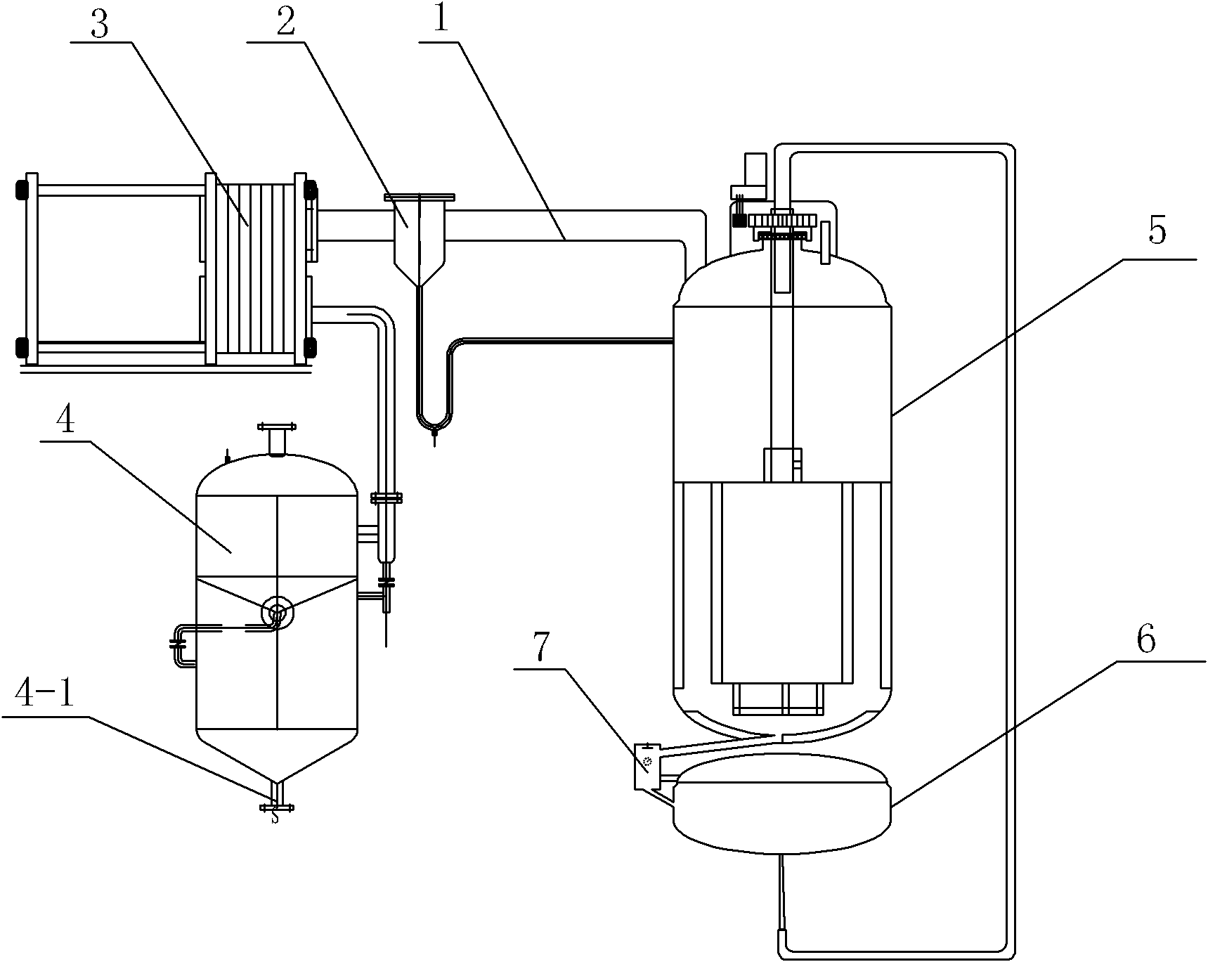
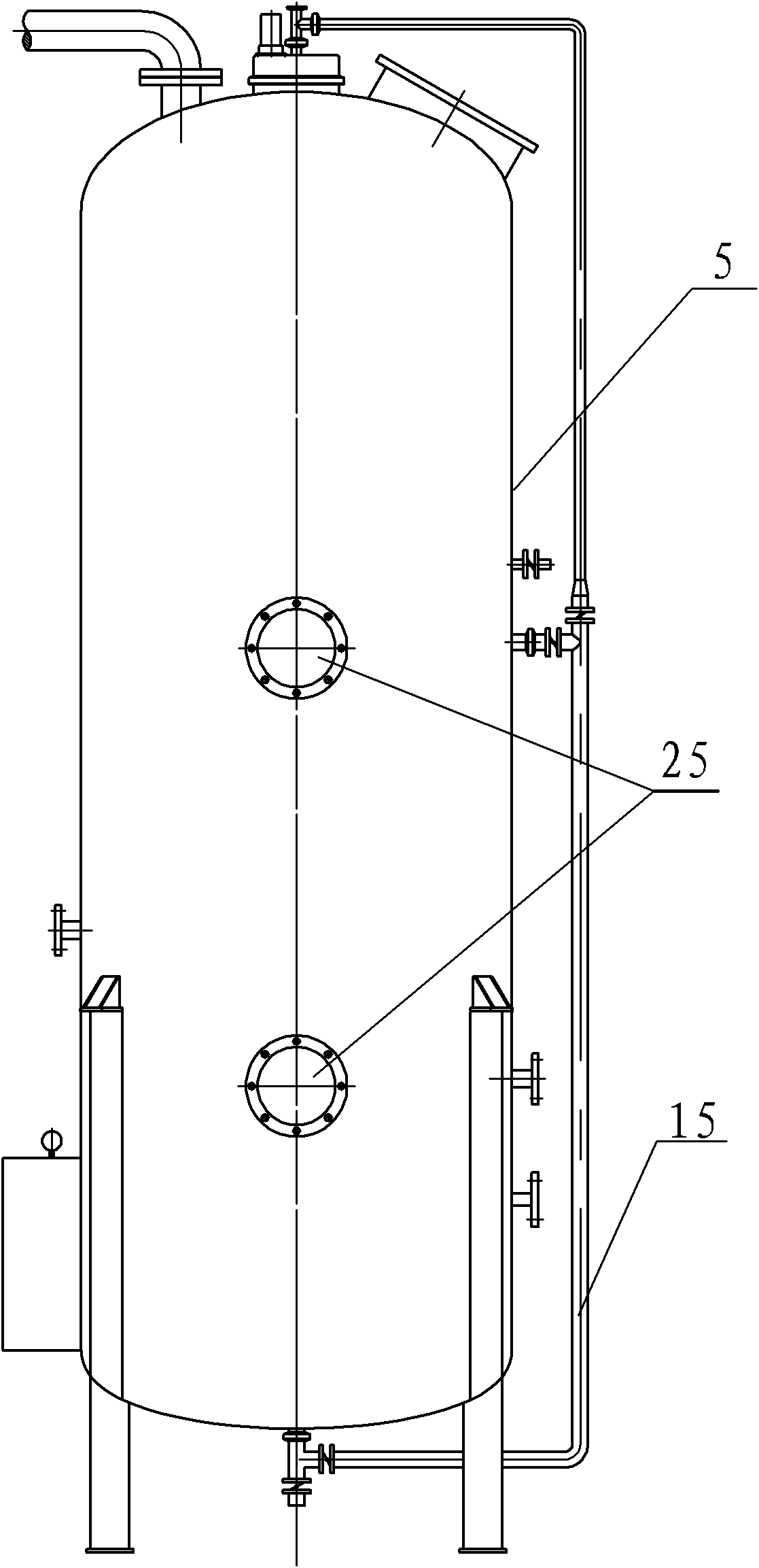
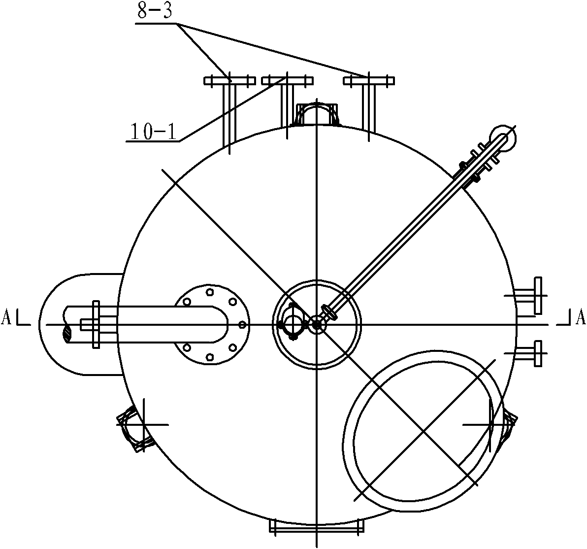
[0008] Specific implementation mode one: combine Figure 1-Figure 8 Description of this embodiment, the concentrator of this embodiment includes an evaporation tube 1, a vapor-liquid separator 2, a condenser 3 and a recovery liquid collector 4, and the bottom of the recovery liquid collector 4 is provided with a recovery liquid discharge port 4-1 , one end of the vapor collection pipe 1 communicates with the inlet of the vapor-liquid separator 2, the outlet of the vapor-liquid separator 2 communicates with the inlet of the condenser 3, and the outlet of the condenser 3 communicates with the inlet of the recovery liquid collector 4 The concentrator also includes a material distribution device, an evaporation tank 5, a collection tank 6, a density measuring device 7, an intermediate jacket 8, an outer jacket 9, a bottom jacket 10, a condensate drain pipe 11, a discharge pipe 13, The total feed pipe 14, the first sub-feed pipe 15, two steam inlet pipes 12 and two sight mirrors 25...
specific Embodiment approach 2
[0010] Specific implementation mode two: combination Figure 7 and Figure 8 Describe this embodiment, the distribution device of this embodiment comprises motor 16, pinion gear 17, bull gear 18, sealing cover 19, second feed pipe 20, feed pipe 21, bowl-shaped distribution pool 22, two first cloth Pipe 23 and two second distributing pipes 24, the output shaft of motor 16 is arranged in the sealing cover 19, and pinion 17 is housed on the output shaft of motor 16, and pinion 17 is meshed with bull gear 18, and the second feed pipe 20 One end passes through the upper end surface of the sealing cover 19 and is arranged in the sealing cover 19 and communicates with one end of the feeding pipe 21. The feeding pipe 21 is equipped with a large gear 18, and the other end of the feeding pipe 21 passes through the upper head and the bowl of the evaporation tank 5. Type distribution pool 22 is fixedly connected and communicated, feeding pipe 21 is coaxially arranged with bowl type distr...
specific Embodiment approach 3
[0011] Specific implementation mode three: combination Figure 4 This embodiment is described. The intermediate jacket 8 of this embodiment is composed of an inner cylinder 8-1 and an outer cylinder 8-2. The top diameter of the inner cylinder 8-1 gradually expands, and the top diameter of the outer cylinder 8-2 Gradually shrinking, the outer diameter of the top of the inner cylinder 8-1 is equal to the inner diameter of the top of the outer cylinder 8-2, and the diameter of the virtual circle formed by the rotation of the two second distribution pipes 24 with the feed pipe 21 as the axis is the same as that of the inner diameter of the inner cylinder 8-1. The topmost inner diameter of the cylinder 8-1 is equal, and the diameters of the top and bottom of the outer jacket 9 gradually expand. This structure can evenly arrange the material liquid flowing out of the second distribution pipe 24 on the inner wall and the inner wall of the inner cylinder 8-1. On the outer wall of the ...
PUM
 Abstract
Description
Claims
Application Information
 - R&D
- Intellectual Property
- Life Sciences
- Materials
- Tech Scout
- Unparalleled Data Quality
- Higher Quality Content
- 60% Fewer Hallucinations
Browse by: Latest US Patents, China's latest patents, Technical Efficacy Thesaurus, Application Domain, Technology Topic, Popular Technical Reports.
© 2025 PatSnap. All rights reserved.Legal|Privacy policy|Modern Slavery Act Transparency Statement|Sitemap|About US| Contact US: help@patsnap.com


