

Quantum dot implant reflection type active grating and manufacturing method thereof
A quantum dot, reflective technology, applied in diffraction grating, optics, opto-mechanical equipment, etc., can solve the problems of limited light-gathering ability and low signal-to-noise ratio, to solve the problem of poor signal strength, solve the problems of mass manufacturing, cost reduced effect
Inactive Publication Date: 2011-06-15
XI AN JIAOTONG UNIV
View PDF3 Cites 22 Cited by
- Summary
- Abstract
- Description
- Claims
- Application Information
AI Technical Summary
Problems solved by technology
Method used
View moreImage
Smart ImageViewing Examples

Examples
Embodiment Construction
Login to View More PUM
| Property | Measurement | Unit |
|---|---|---|
| height | aaaaa | aaaaa |
Abstract
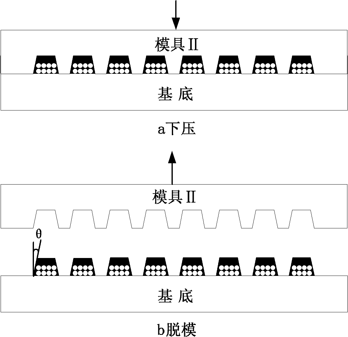
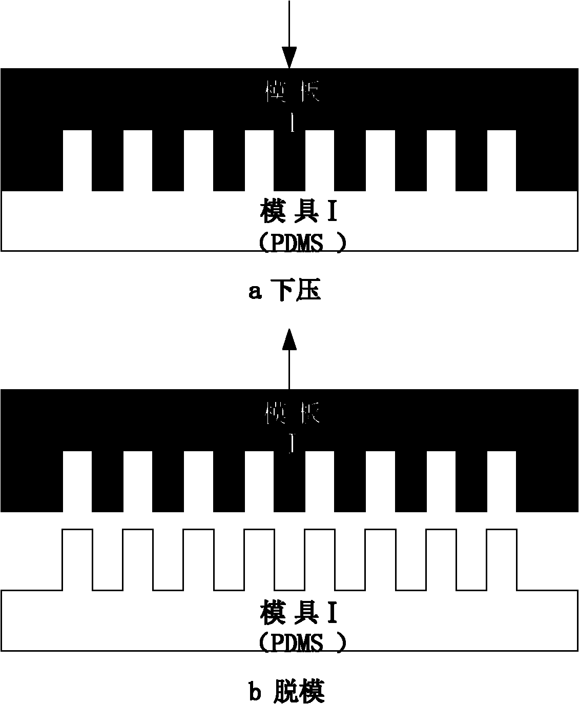
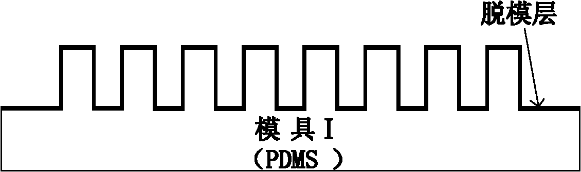
The invention discloses a quantum dot implant reflection type active grating and a manufacturing method thereof, wherein the quantum dot is firstly embedded in a grating structure by means of impressing process based on the excellent photoluminescence capability of the quantum dot and the wide chromaticity selection range, the light emitted by the quantum dot and the light reflected by the grating are jointly diffracted by means of structural design and selection for the type of the quantum dot, and the diffraction effect is increased. The manufacturing process provided by the invention is as follows: the quantum dot and the grating mould are manufactured by means of electron beam lithography and vacuum casting method, microstructure patterns of the quantum dot and the grating are manufactured by means of impressing process, and the grating structure is formed finally. The period of the grating is 20 nm to 20 microns, the groove width is 20 nm to 20 microns, and the height is 20 nm to 20 microns; the microstructure of the grating is cylindrical, square, rectangular, rhombic or hexagonal and trapezoidal and the like; the included angle between the edge of the microstructure and the vertical direction is controllable, and the range of the included angle is 0 to 90 DEG.
Description
Quantum dot implanted reflective active grating and manufacturing method thereof Technical field: The invention belongs to the technical field of micro-nano manufacturing, and relates to a novel drag-reducing surface and a manufacturing method thereof, in particular to a quantum dot implanted reflective active grating and a manufacturing method thereof. Background technique: Grating technology has been widely used in precision displacement measurement and angle measurement. It is widely used in CNC machining, microelectronics and other fields. As one of the core technologies of CNC machine tools, grating measurement technology plays a decisive role in ensuring the various performance indicators of modern machine tools. However, the grating measurement also has the following problems: it is difficult to engrave a grating with a high number of lines and a large length, which is reflected in the contradiction between the measurement resolution and the range in the length mea...
Claims
Login to View More Application Information
Patent Timeline
 Patent Type & AuthorityApplications(China)
IPC IPC(8): G02B5/18G03F7/00
Inventor刘红忠丁玉成徐维卢秉恒
OwnerXI AN JIAOTONG UNIV