Soft switching inverting circuit and control method thereof

A technology of inverter circuit and control method, which is applied in the direction of electrical components, high-efficiency power electronic conversion, AC power input conversion to DC power output, etc., can solve the problems of increasing the additional cost of the system and control complexity, and achieve the purpose of overcoming reverse recovery Issues, Device Selection Reduction, Efficiency Enhancement Effects

Inactive Publication Date: 2012-10-24
XIAN UNIV OF SCI & TECH
View PDF1 Cites 0 Cited by
  • Summary
  • Abstract
  • Description
  • Claims
  • Application Information

AI Technical Summary

Problems solved by technology

[0007] However, these technologies still have shortcomings: three auxiliary switches need to be added to the resonant auxiliary circuit, and at the same time, three auxiliary switches require three sets of drive units and drive power supplies, which increases the additional cost of the system and the complexity of control

Method used


Image

  • Soft switching inverting circuit and control method thereof
  • Soft switching inverting circuit and control method thereof
  • Soft switching inverting circuit and control method thereof

Examples


Embodiment 1

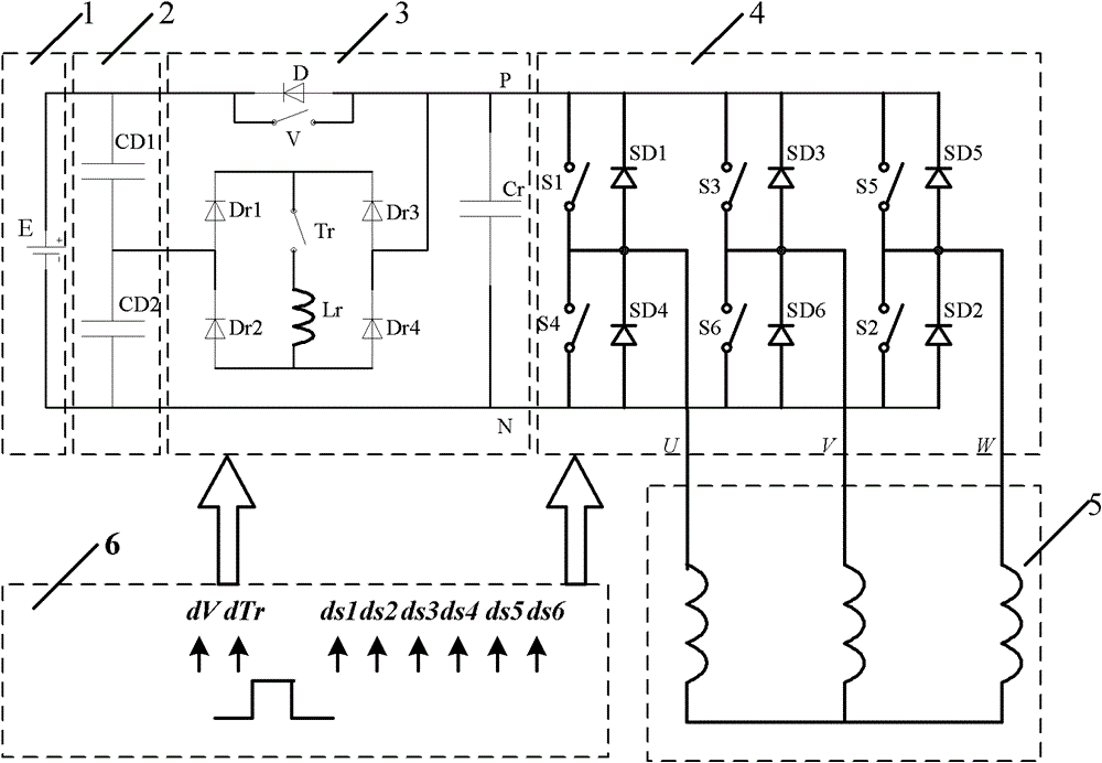
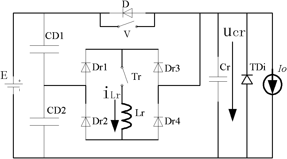
[0057] Such as figure 1 A soft-switching inverter circuit shown includes a control circuit 6, a DC power supply 1, and an inverter bridge 4 that converts DC power into AC power. The output terminal of the DC power supply 1 is connected to a voltage divider circuit 2 and is reversed through a DC bus. The variable bridge 4 provides power, and the inverter bridge 4 is connected to the control circuit 6, characterized in that: a resonance auxiliary circuit 3 is connected between the voltage divider circuit 2 and the inverter bridge 4, and the resonance auxiliary circuit 3 consists of two Auxiliary switches V and Tr, a single-phase rectifier bridge, a capacitor Cr, a diode D and an inductance Lr, the single-phase rectifier bridge is composed of diodes Dr1, Dr2, Dr3 and Dr4, the single-phase rectifier One AC end of the bridge is connected to the midpoint of the voltage divider circuit 2, the other AC end of the single-phase rectifier bridge is connected to the P pole of the DC bus, a...

Embodiment 2

[0076] Such as Figure 5 As shown, a soft switching inverter circuit is provided, which is used to drive a three-phase permanent magnet brushless DC motor 7. In this embodiment, on the basis of embodiment 1, the inductive load 5 is replaced with a specific three-phase permanent magnet brushless DC motor 7. The circuit structure of the remaining parts is the same as that of embodiment 1, and the working principle is the same as that of embodiment 1. I won't repeat it here. Here, the simulation is mainly performed on this embodiment. In the simulation, the three-phase permanent magnet brushless DC motor 7 works in the well-known star-shaped three-phase six-state. Its parameters are: rated power 40W, rated voltage 24V, number of poles 4, winding resistance per phase 0.95Ω, winding per phase The inductance is 0.829mH. In this embodiment, the parameters of the resonance auxiliary circuit 3 are: capacitance Cr=22nF, resonance inductance Lr=5uH. The voltage of the known DC power su...


PUM


Abstract

The invention discloses a soft switching inverting circuit and a control method thereof. The soft switching inverting circuit comprises a control circuit, a direct current power source, a partial pressure circuit and an inverting bridge, wherein a resonance auxiliary circuit is connected between the partial pressure circuit and the inverting bridge, the resonance auxiliary circuit comprises two auxiliary switches V and Tr, a single-phase inverting bridge, a capacitor Cr, a diode D and an inducer Lr, the single-phase inverting bridge consists of diodes Dr1, Dr2, Dr3 and Dr4, and the resonance auxiliary circuit is connected with the control circuit and is used for controlling the switching on and off of the auxiliary switches V and Tr according to signals dV and dTr transmitted by the control circuit; and the soft switching inverting circuit has the control method that the control circuit transmits a control signal to reasonably control the switching on and off of the auxiliary switchesV and Tr when a power device of the inverting bridge needs to be switched into another switching status from one switching status. After the invention is used, the defects that the additional cost ishigh, the control is complex, the power density of the inverter is low and the like in the prior art are overcome, the power density of the inverter is improved, the electromagnetic interference is reduced, and the control method is simple and easy to realize.

Description

Technical field [0001] The invention belongs to the technical field of inverters, and in particular relates to a soft switch inverter circuit and a control method thereof. Background technique [0002] At present, most bridge inverters use hard-switching pulse width modulation (PWM) technology. In PWM inverters, the volume and weight of output transformers, filter inductors, and heat sinks account for the main part. In order to reduce the power electronic device In order to increase the power density of the inverter in terms of volume and weight, the switching frequency of the inverter power switching device must be increased. However, after the high frequency, the switching loss of the power switching device increases sharply, causing the junction temperature of the power switching device to rise sharply, preventing the high frequency of the power conversion circuit; and the power switching device has a large voltage and current after the high frequency. The rate of change (du / ...

Claims


Application Information

Patent Timeline
Patent Type & Authority Patents(China)
IPC IPC(8): H02M7/5395H02M1/44
CPCY02B70/1491Y02B70/10
Inventor 贺虎成
Owner XIAN UNIV OF SCI & TECH
Why Eureka
Try Eureka