Apparatus for treating discharge gas and system for treating discharge gas

A waste gas treatment device and waste gas technology, applied in gas treatment, combustion product treatment, chemical/physical processes, etc., can solve the problems of inapplicable large-capacity waste gas treatment, etc., and achieve the effect of increasing contact time

Inactive Publication Date: 2011-06-15
MITSUBISHI HEAVY IND LTD
View PDF4 Cites 4 Cited by
  • Summary
  • Abstract
  • Description
  • Claims
  • Application Information

AI Technical Summary

Problems solved by technology

[0005] As a method for treating metallic mercury in exhaust gas, removal methods using adsorbents such as activated carbon or selenium filters are known, but ...

Method used


Image

  • Apparatus for treating discharge gas and system for treating discharge gas
  • Apparatus for treating discharge gas and system for treating discharge gas
  • Apparatus for treating discharge gas and system for treating discharge gas

Examples


Embodiment

[0049] An exhaust gas treatment system to which an exhaust gas treatment device according to an embodiment of the present invention is applied will be described with reference to the drawings.

[0050] In addition, because the configuration and Figure 8 The shown exhaust gas treatment system has the same configuration, so in this embodiment, the configuration of the exhaust gas treatment device will be described.

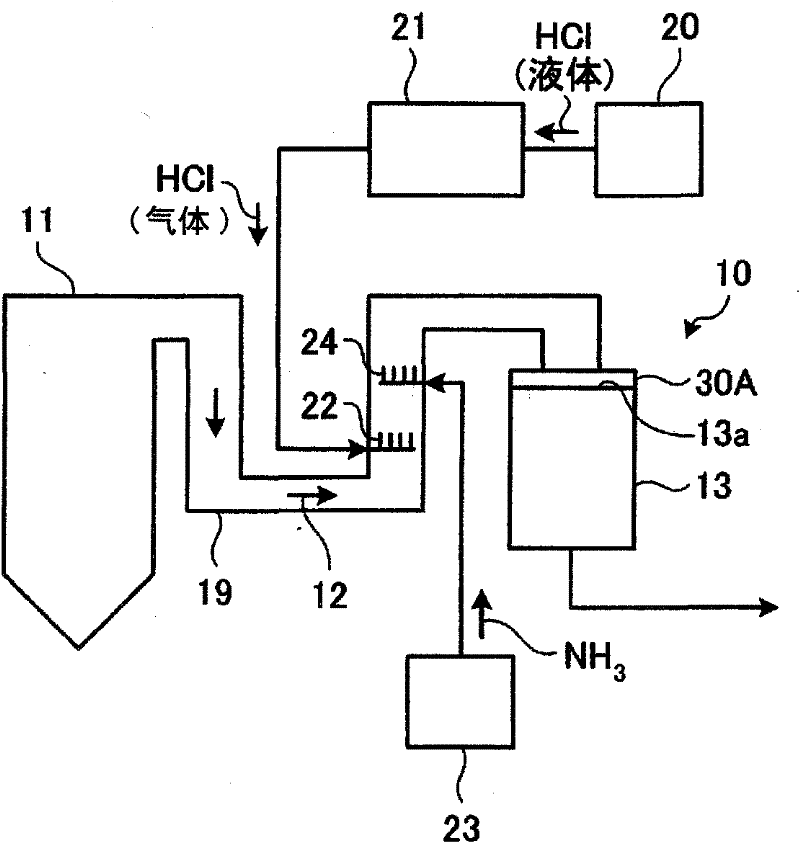
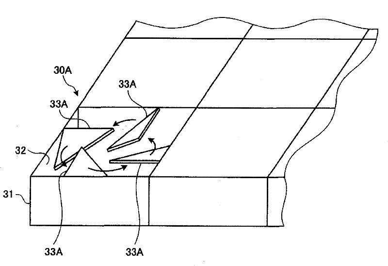
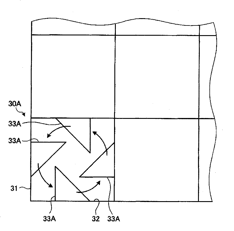
[0051] figure 1 It is a schematic diagram showing the exhaust gas treatment device of the embodiment, figure 2 is a perspective view of the vortex generating part, image 3 This is a view of the swirl flow generating member viewed from the axial direction.

[0052] in addition, figure 1 is composed of Figure 8 Since it is a part of the exhaust gas treatment system shown, the same symbols will be added to the same components as those of the existing ones, and repeated descriptions will be omitted.

[0053] Such as figure 1 As shown, the exhaust gas treatme...


PUM


Abstract

An apparatus for discharge gas treatment (10) having a denitration catalyst layer (13) which removes NOX from a discharge gas (12) and in which HCl is sprayed in the discharge gas (12) to oxidize mercury. The apparatus has a spiral-flow generation member (30A) disposed on an inlet (13a) side of the denitration catalyst layer (13). The member (30A) is constituted of: a spiral-flow generation member main body which has been partitioned so as to correspond to individual passages of the denitration catalyst layer (13); and a plurality of spiral-flow generation blades which have been disposed on the inner walls of each of the separated chambers and cause a turbulent flow. This configuration changes the flow of the discharge gas (12), which is a laminar flow in a flue (19), into a spiral flow inside the denitration catalyst layer (13). The time period of contact of the discharge gas (12) with the denitration catalyst can hence be prolonged to improve the efficiency of the oxidation reaction of the mercury contained in the discharge gas (12) with the denitration catalyst.

Description

technical field [0001] The present invention relates to an exhaust gas treatment device and an exhaust gas treatment system for treating exhaust gas discharged from a combustion device. Background technique [0002] Since waste gas discharged from a coal-fired boiler, which is a combustion device such as a thermal power station, contains highly toxic mercury, various studies have been made on systems for removing mercury in the waste gas. [0003] Generally, a coal-fired boiler is provided with a wet desulfurization device for removing sulfur components in exhaust gas. It is known that when the amount of chlorine (Cl) in the exhaust gas increases, the ratio of divalent metallic mercury (Hg) soluble in water to the flue gas treatment facility formed by adding a desulfurization device to such a boiler is known. Large, easy to capture mercury with the desulfurization device. [0004] Therefore, in recent years, the reduction of NO x The denitrification device, and the alkali...

Claims


Application Information

Patent Timeline
IPC IPC(8): B01D53/94B01D53/64B01J35/04F23J15/00
CPCF23J2215/10F23J2219/10F23J15/003B01D2251/108B01D2255/20746B01D2255/20738B01D2257/302B01D2255/102B01D2255/20723B01D53/8631B01D2255/20769B01D2255/20753B01D53/64B01D2255/20776B01D2257/602F23M9/003F23J2215/60
Inventor 佐藤敏浩坂田展康四条利久磨村上盛纪鹈饲展行野地胜己清泽正志
Owner MITSUBISHI HEAVY IND LTD
Why Eureka
Try Eureka