Charging power supply system

A charging power supply and power supply technology, applied in the direction of electrical components, output power conversion devices, irreversible AC power input conversion to DC power output, etc., can solve the impact of power grid stability, invest a lot of construction costs, and the power grid cannot provide enough Electricity and other issues to achieve the effect of increasing the pressure on the power grid, improving equipment investment costs, improving power supply quality and efficiency

Inactive Publication Date: 2011-06-29
丰汇新能源有限公司
View PDF3 Cites 27 Cited by
  • Summary
  • Abstract
  • Description
  • Claims
  • Application Information

AI Technical Summary

Problems solved by technology

However, there are still some constraints in the current charging infrastructure construction, among which providing charging and swapping power for electric vehicles anytime and anywhere is the biggest problem
[0003] The first is the question of where to build the charging station. If the existing gas station is transformed into a comprehensive service station that integrates charging, battery replacement, and refueling, it is currently impossible to realize, because the gas station uses civilian electricity and cannot adapt to large-capacity batteries. The charging needs of electric vehicles require higher voltage and higher current, so the existing gas stations must be rebuilt to provide high-power industrial electricity; moreover, the existing gas station design is also difficult to meet the requirements of safe charging. requirements, and safety is one of the most important requirements for electric vehicle charging stations
If charging stations are built in existing private car parking lots, business and public car parking lots, or newly-built real estate and community parking lots, since the charging stations include chargers, power monitoring systems, active filter devices, power output devices, transformers, distribution Electric cabinets, cables and other equipment, among which the primary side of the transformer is generally connected to a 10KV or 35KV transmission line. The transformer has a large power and a large volume, which requires a site. The charging station occupies a large area and generally requires a substation size. Generally, overhead lines cannot enter the city. However, the laying of cables with special specifications requires digging trenches on the road surface. Not only is the land use difficult to secure, but it is also difficult to realize the reconstruction of line laying, which requires a lot of construction costs. Moreover, it is often impossible to build a large number of charging stations in the city center because of the objections of the surrounding residents.
[0004] The second problem is whether high-power charging power can be supplied with guaranteed quality and quantity. At present, my country's power resources are still in short supply, especially during peak hours, when my country's power grid is often at full load, and random charging of large-scale electric vehicles will generate a large amount of load. , if a large number of electric vehicles are charging at the same time, it will bring difficulties to the grid peak regulation, because the grid cannot provide enough power, which may cause the transmission grid to trip
Moreover, it takes a long time for electric vehicles to complete charging, and the AC and DC power conversion will be completed during the charging process, which will have a great impact on the stability of the power grid and affect the normal power supply and user charging quality
[0005] The third problem is the inconvenient charging of electric vehicles. The charging power of electric vehicles is generally about 30KW, and the charging current is nearly 100A. For high-level and long-distance travel, if there is no charging station within the maximum cruising range, the electric vehicle used will have the risk of stopping midway
In addition to the limitation of the charging environment, due to the limitation of battery technology, fast charging cannot be reliably realized at present, so that the charging time of electric vehicles cannot reach the speed of the current refueling time, and relying on the technology and conditions of existing charging facilities, it cannot meet The need for electric vehicles to realize slow charging through peak avoidance will increase the charging cost, which will greatly weaken the economical advantages of new energy vehicles
[0006] The fourth difficulty is that the charging model of the charging infrastructure is not unified, and the charging model, charging operation model and infrastructure construction have not been considered together, and the interaction between the charging station and the developing smart grid has not been considered. Guarantee the safety, versatility and interchangeability of charging
These solutions can solve some partial links in the above problems, but cannot fundamentally and comprehensively solve the aforementioned problems

Method used


Image

  • Charging power supply system
  • Charging power supply system
  • Charging power supply system

Examples


Embodiment Construction

[0036] The specific embodiments of the charging power supply system of the present invention will be described in detail below with reference to the accompanying drawings, but the present invention is not limited to the description of the following embodiments.

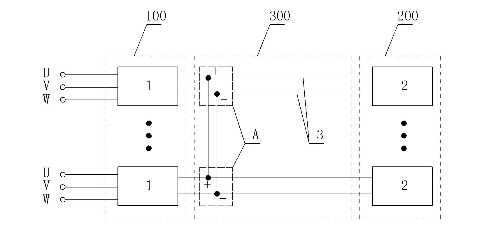
[0037] figure 1 It is a schematic diagram of the basic structure of the charging power supply system of the present invention. It illustrates the power collector 1 and the power collector group 100, the transmission cable 3 and the DC power supply network 300, the power output device 2 and the power output device group 200 that constitute the charging power supply system. The connection relationship between. Such as figure 1 As shown, the output ends of a plurality of power collectors 1 with the same DC output voltage are connected in parallel to form a power collector group 100, and the output ends of each power collector 1 are connected in parallel through a power transmission cable 3 to form a DC power supply network 3...


PUM


Abstract

The invention discloses a charging power supply system. The charging power supply system comprises a power acquisition device group, a power output device group and transmission cables, wherein the power acquisition device group consists of power acquisition devices; the power output device group consists of power output devices; the transmission cables are used for transmitting high-voltage direct-current power output from the power acquisition devices to the power output devices; the input ends of each of the power acquisition devices are respectively connected with a secondary side of a transformer or a power bus; the direct-current voltages output from the power acquisition devices are equal to each other; the output ends of each of the power acquisition devices are connected in parallel through the transmission cables to form a direct-current power network of which the electric potentials at each point are the same; the input ends of each of the power output devices are connected with any node A in the direct-current power network (300) through the transmission cables; and the output ends of the power output devices provide direct-current power for various charging loads. Power is dynamically acquired from low-ebb users by the power acquisition devices according to a tidal electricity utilization state and the frequency, the pulse width and the conduction interval of power switching devices are dynamically modulated, so that the power supply quality is improved, reactive power, harmonic waves or a negative sequence current are utilized, the no-load power of the transformer and the low-ebb electricity of a power grid are called, and an important base support system is provided for the development of new energy vehicles.

Description

Technical field [0001] The invention relates to an AC and DC dual-purpose charging power supply system, especially a high-power charging power supply system, belonging to the technical field of high-voltage and high-current power electronics applications, and can be used for various specifications of electric cars, buses, buses, and sightseeing cars , And the charging and replacement of electric vehicles such as trucks, or other industrial and civilian charging and replacement. Background technique [0002] With the implementation of the national energy development strategy and the implementation of key support policies for new energy, energy conservation and environmental protection and other emerging industries, people's awareness of energy conservation and emission reduction has continued to increase, and the development of new energy and energy conservation and environmental protection industries has been very rapid. Taking new energy vehicles as an example, the trend of elec...

Claims


Application Information

Patent Timeline
Patent Type & Authority Applications(China)
IPC IPC(8): H02M7/02H02M5/458H02M7/06
Inventor 马志刚
Owner 丰汇新能源有限公司
Why Eureka
Try Eureka