
Washing device and washing method for marine exhaust flue gases

A technology of washing device and washing method, applied in the direction of separation method, chemical instrument and method, use of liquid separating agent, etc.

Active Publication Date: 2013-06-19
CLEAN ENERGY PROJECT TECH INC
View PDF3 Cites 9 Cited by
  • Summary
  • Abstract
  • Description
  • Claims
  • Application Information

AI Technical Summary

Problems solved by technology

[0008]2) At the same time, the scrubber uses a hollow fiber membrane contactor to realize the washing function, the pressure drop and resistance are very large, and the addition of a booster fan will reduce the energy consumption and cost of system operation very high
The pressure loss of the bubbling washing method is the energy loss of the exhaust to overcome the liquid pressure, which basically corresponds to the liquid column pressure at the depth of the exhaust immersion in the liquid; that is to say, the better the washing effect, the greater the pressure loss and the higher the operating cost. High, the contradiction between washing effect and operating cost is basically irreconcilable
[0018] Under the condition of using seawater as the washing liquid, the operating pressure loss of the patented technical solution is required to be less than 6 inches (152mm) of water column, obviously its exhaust smoke is immersed in the washing liquid The depth is also less than 6 inches. With such a shallow immersion depth, even if supplementary technical measures are taken to increase "mixing blades" to form turbulence and disperse air bubbles, the total liquid-gas contact area is extremely limited, and the washing and absorption rates are still very low. ; To significantly improve the washing effect, it is necessary to increase the immersion depth of the exhaust gas, increase the pressure loss, increase energy consumption and operating costs, and the effect is obviously not good
[0019]2) The contradiction between cooling high-temperature flue gas and low-temperature absorption of sulfur dioxide is difficult to overcome
The cooling, washing and absorption of high-temperature flue gas in this invention is mainly carried out by the same pool of water. The temperature of seawater washing will rise while cooling high-temperature flue gas, and the heated seawater is also used to wash and absorb sulfur dioxide at the same time, so that the absorption rate of sulfur dioxide cannot be increased. ; and to improve the absorption rate, only by increasing the amount of washing water can the temperature rise of washing sea water be reduced, which will lead to a substantial increase in energy consumption and operating costs, and the process will lose sight of the other.
[0021]3) The contradiction between anti-corrosion reducing operating cost and increasing manufacturing cost is difficult to overcome
However, the heat pipe must have a complex cross-section such as a star shape to increase its heat conduction area so that more heat can be used to reheat the exhaust gas. Since the heat exchanger works in a high-temperature, high-humidity, and strong corrosive environment, the structure is complex , it needs to use a large amount of corrosion-resistant alloy materials, which will inevitably greatly increase the manufacturing cost of the device, but will lead to an increase in the overall use cost, and the result is not worth the candle
[0023]4) The contradiction between corrosion prevention and corrosion aggravation of reheated flue gas is difficult to overcome
[0026]Obviously, in order to solve the problem of high-temperature flue gas treatment from 200°C to 490°C of sea-going ship engines, the prior art has adopted low-efficiency and high-cost methods and devices
Based on the above status quo, the long-awaited technical principle of using seawater washing to reduce ship pollution has not been able to become a practical technical solution

Method used


Image

  • Washing device and washing method for marine exhaust flue gases
  • Washing device and washing method for marine exhaust flue gases
  • Washing device and washing method for marine exhaust flue gases

Examples


Embodiment 1

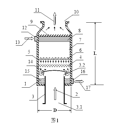
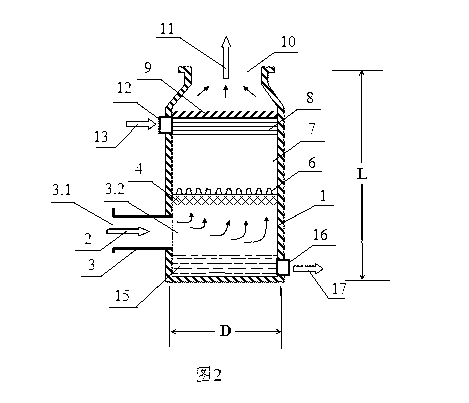
[0089] The flue gas inlet 3.2 in the housing 1 is fixed at the bottom of the housing 1 and extends to the outlet of the flue gas duct 3 inside the housing 1. There is a right to the outlet for preventing washing seawater from entering the flue gas duct 3. The liquid collecting cover 14;

[0090] The flue gas inlet 3.2 in the housing 1 is a through hole on the side wall of the housing 1, or the outlet of the flue gas duct 3 fixedly connected to the side wall of the housing 1;

[0091] The liquid collection pool 15 is composed of the lower side wall and the bottom of the housing 1 and the pipe wall of the flue gas conduit 3, and can also be fixed by a partition outside the pipe wall. A partition can prevent the pipe wall of the flue gas conduit 3 from Corroded;

[0092] The material of the high-temperature-resistant component that forms the cooling uniformity layer 4' is a high-temperature-resistant inorganic material. This example uses a ceramic material, or a metal material, ...

Embodiment 2

[0102] The difference from the above-mentioned embodiments is that the cooler 4 is installed on the flue gas duct 3, and can also be a water spray system connected to the housing 1 for spraying cooling water into the high-temperature flue gas 2. The water spray system For the combination nozzle.

Embodiment 3

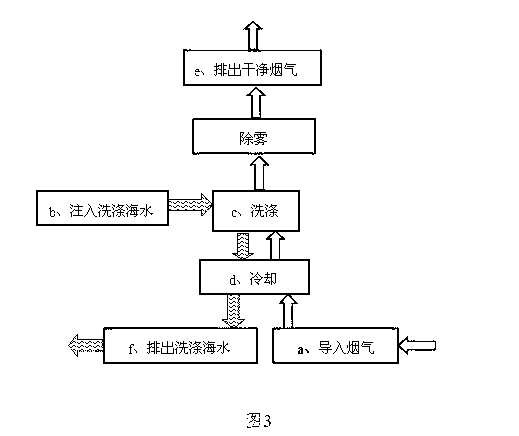
[0103] B, the embodiment of the sea-going ship smoke exhaust cleaning method of the present invention.


PUM


Abstract

This invention relates to a ship flue gas scrubbing apparatus and scrubbing method. The apparatus includes a housing (1), an upper scrubbing layer (7) at the upper side inside the housing (I), and a liquid collecting pool (15) in the lower side inside the housing (1), a flue gas leading-in port (3.2) between the scrubbing layer (7) and the liquid collecting pool (15), a scrubbing seawater inlet (12) above the scrubbing layer (7), and a cooler (4) located at a flue gas passage between the flue gas inlet (3.1) outside the housing and the scrubbing layer (7). The method includes leading flue gas, cooling, injecting scrubbing seawater, scrubbing and other steps.

Description

technical field [0001] The invention relates to a sea-going ship smoke exhaust washing device and a washing method, which use seawater to wash and reduce the emission of pollutants mainly sulfur dioxide in the sea-ship ship smoke, and belong to the technical field of atmospheric environmental protection and sea-going ship smoke pollution prevention and control. Background technique [0002] Over the past 20 years, the international legislation to reduce emissions of gaseous pollutants mainly sulfur dioxide emitted by industrial facilities has been gradually tightened and improved. In recent years, the restricted objects have developed from land-based industrial facilities to sea-based ships. [0003] After the issue of reducing sulfur dioxide emissions from ships was raised globally, there was a trend of emphasizing seawater flue gas desulfurization technology. In 2007, a research report by a joint institution of four internationally renowned universities clearly stated tha...

Claims


Application Information

Patent Timeline
Patent Type & Authority Patents(China)
IPC IPC(8): B01D53/78B01D53/50
CPCB01D2257/302B01D2259/4566B01D53/1481B01D53/78B01D53/507B01D53/18B01D2252/1035B01D2258/012B01D47/02B01D47/14
Inventor 彭斯干
Owner CLEAN ENERGY PROJECT TECH INC
Learn More