Hydrodynamic machine, and using method and application thereof

A technology of water-driven machinery and water-driven motors, applied in mechanical equipment, engine components, impact engines, etc., can solve problems such as the development of the modern civilization of the Chinese nation

Active Publication Date: 2011-07-13
马瑞志
View PDF7 Cites 19 Cited by
  • Summary
  • Abstract
  • Description
  • Claims
  • Application Information

AI Technical Summary

Problems solved by technology

[0002] In ancient my country, there were waterwheels and mills and other hydrodynamic machines that use the flow energy of water bodies to work. However, because they can only be used on a small scale in small rivers and streams, coupled with prejudices in understanding, this ancient technological contribution of the Chinese nation has no Carried forward by modern civilization

Method used


Image

  • Hydrodynamic machine, and using method and application thereof
  • Hydrodynamic machine, and using method and application thereof
  • Hydrodynamic machine, and using method and application thereof

Examples


Embodiment 1

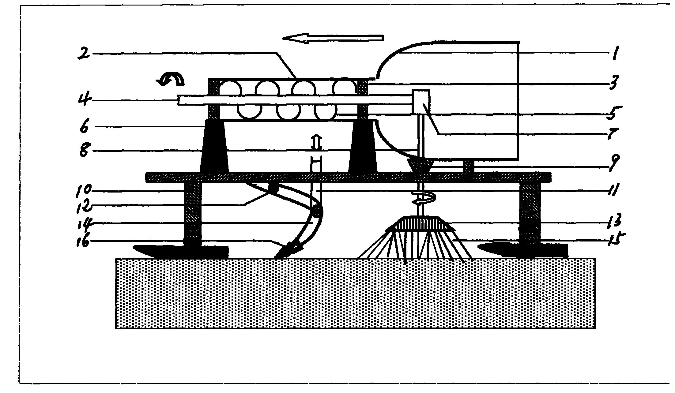
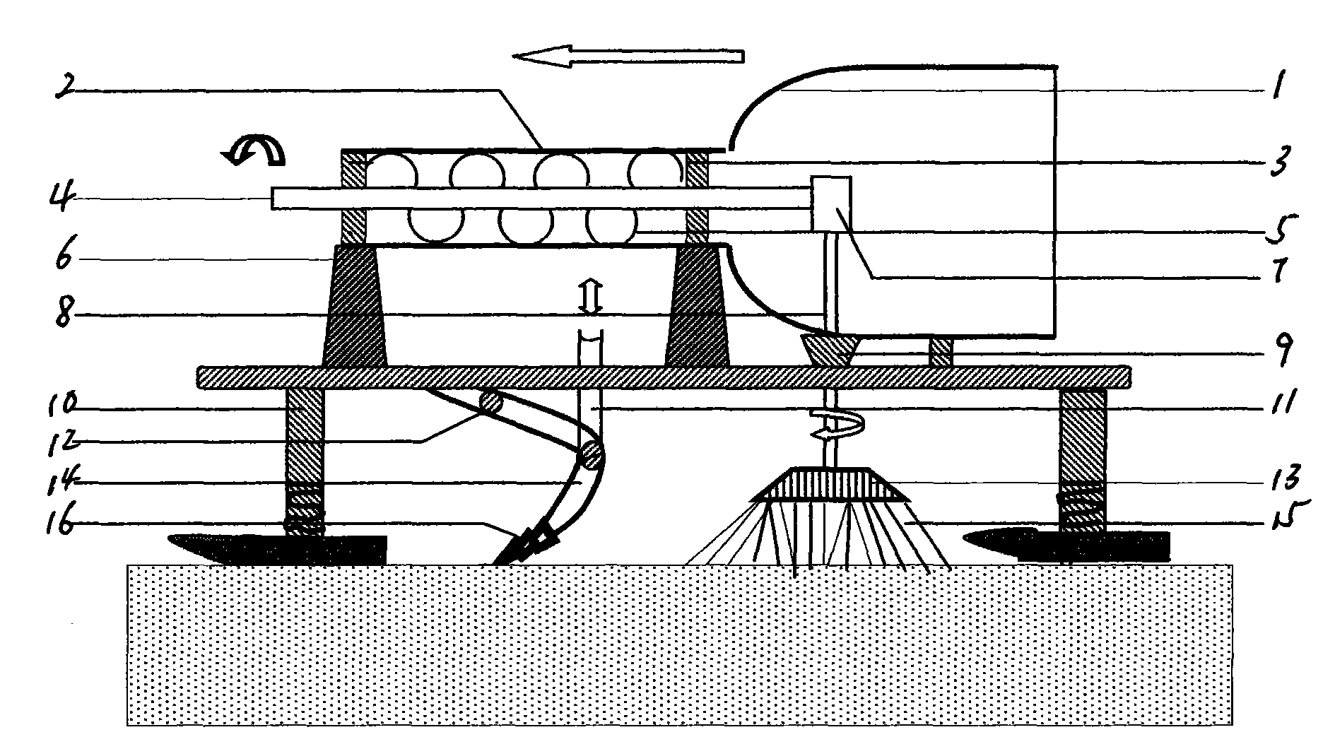
[0020] Embodiment 1, the operation method of the river dredging ship. The river channel dredging ship is equipped with the control mechanism and operating system of the underwater working platform. Pile piers can be set up on the ship, and a pair of shafts that drag and control the traveling direction of the underwater working platform can be installed with a fixed hinge connection. The far end of the lower working platform is provided with a hoisting steel cable, so that the orientation and delivery height of the underwater working platform can be controlled on board. In order to ensure that the water motor has a relatively large working water flow rate, the speed of the ship's drifting along the water must be controlled. The underwater working platform itself has the function of dragging the hull, and the horizontal sediment disturbance machine and bucket dredger work. Produces a force that restrains the ship from advancing. The self-propelled plowing machine is a mechanism...

Embodiment 2

[0021] Embodiment two, the structure and working mode of the paddle-wheel type water motor of the water model. When the water-type paddle-wheel water motor is in the working position, the water flow will naturally push the blades to make the runner rotate. The sliding extended paddle 29 is installed on the sliding track of the spoke 22. When the spokes moved below the horizontal line of the incoming water direction and began to incline downward, the sliding paddle 29 automatically slid out of the rim by its own gravity and the sliding mechanism on the slide rail, and when it slid to the set end position, the sliding paddle moved forward and backward. The stopper 28 is blocked by the front stopper 27 of the band rubber pad, and continues to move forward downwards with the runner under the promotion of the water flow. When the sliding paddle 29 leaves the water surface and moves above the horizontal line, it will automatically slide back to the wheel hub 23 by its own gravity a...


PUM


Abstract

The invention discloses a hydrodynamic machine, and a using method and application thereof, and belongs to the technical field of development and utilization of new energy source, namely water flowing energy source. Because of shortage of applicable mechanical equipment and an implementation method, the most abundant and cleanest renewable energy source, namely water flowing energy is not put into use yet. A waterwheel type paddle wheel water motor, a screw type water motor, and a combined propeller type water motor are used as prime motors to drive a generator, a pump, a sediment disturbance machine, a disturbance-suction type sediment lifting machine and a bucket sediment excavator working machine so as to form water flow power generation, water diversion irrigation, and channel cleanout mechanical equipment and systems, a water flow power generation station and a water diversion irrigation station are established, a long-range water diversion project is implemented, and an innovative method is provided for comprehensive treatment of river channel sedimentation disasters. Through the mechanical equipment and the using method, a specific and feasible technical scheme is provided for water flow power generation new energy development, implementation of a project of water diversion from Yellow River into the Loess Plateau, and danger elimination of aboveground rivers of the Yellow River, and Huai River.

Description

(1) Technical field [0001] The invention relates to the technical field of development and utilization of water flow energy new energy. (2) Background technology [0002] In ancient my country, there were waterwheels and mills and other hydraulic machinery that use the energy of water flow to work. However, because they can only be used on a small scale in small rivers and streams, coupled with prejudice in understanding, this ancient technological contribution of the Chinese nation has no Carried forward by modern civilization. The flow energy resources of rivers and rivers on land are extremely rich. Due to the lack of suitable mechanical equipment and implementation methods, the technology of converting water flow energy into practical energy is still immature. The floods and river siltation disasters caused by it have long been troubled, and the water resources of the river have not been rationally utilized. The water in the mountains flows away by itself, and the phenom...

Claims


Application Information

Patent Timeline
Patent Type & Authority Applications(China)
IPC IPC(8): F03B13/00F03B13/08F03B1/00F03B3/00E02F5/28E02B9/00E02B13/00E02B3/02
CPCY02E10/223Y02E10/22Y02E10/20
Inventor 马瑞志
Owner 马瑞志
Why Eureka
Try Eureka