Softening process for industrial raw water

An industrial, raw water technology, applied in water softening and other directions, can solve the problems of large process area, large water content, low process efficiency, etc., and achieve the effects of wide process conditions, slow grain growth, and simple process operation.

Active Publication Date: 2011-07-27
白连福
View PDF4 Cites 10 Cited by
  • Summary
  • Abstract
  • Description
  • Claims
  • Application Information

AI Technical Summary

Problems solved by technology

Its disadvantages are: 1. The process efficiency is low, and the filtration rate is 5-7 m/h, so the structure is large in size and large in investment; The amount of water is large, and the subsequent drying treatment is difficult; 3. The process occupies a lot of land and the land cost is high
Its disadvantages are: 1. It needs to consume artificial crystal nuclei continuously, increasing the operating cost; 2. The particle size of artificial crystal nuclei must be strictly matched with th

Method used


Image

  • Softening process for industrial raw water
  • Softening process for industrial raw water
  • Softening process for industrial raw water

Examples


Embodiment 1

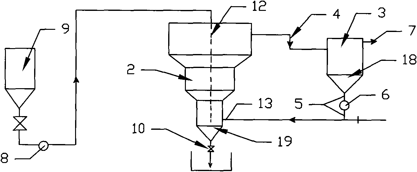
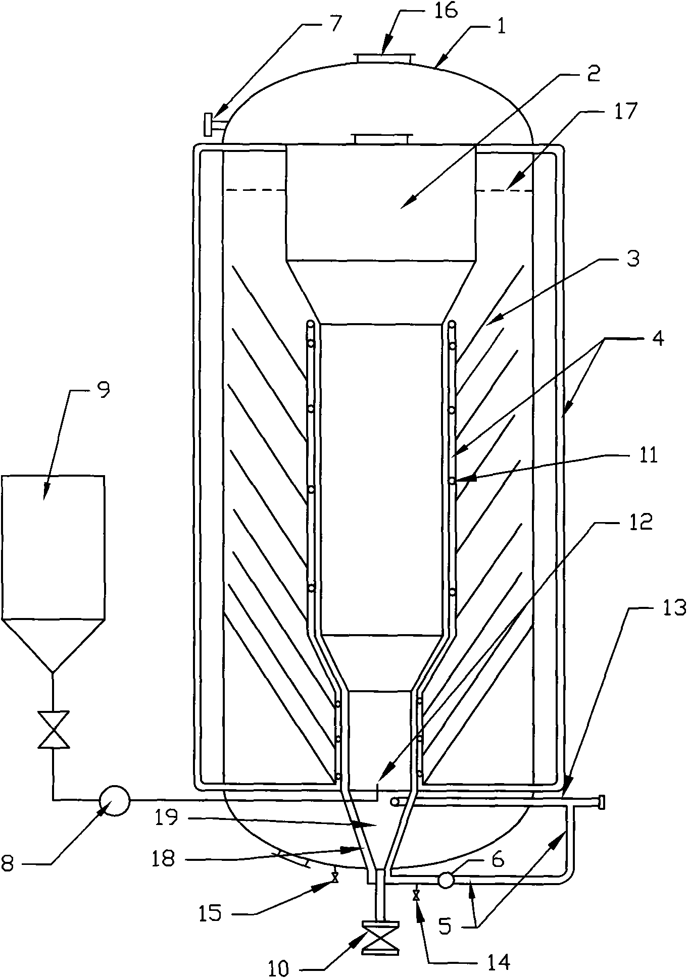
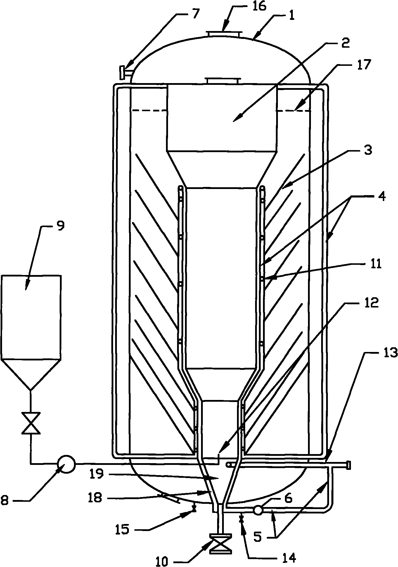
[0018] The schematic diagram of the specific implementation is as follows figure 2 : the main body of the cyclone clarifier (2) is placed in the tank body (1); the main body of the cyclone clarifier (2) is composed of three sections of successively increased cylinders and two sections of truncated cone tubes, and the lower part is provided with There is an offset water inlet pipe (13), its upper part is connected to the water delivery pipe (4), and its bottom is provided with a sand discharge valve (10) and a conical inner sand collection bucket (19). The external sand bucket (18) is covered with a certain gap, and the external sand bucket (18) is connected with the sedimentation device (3); a sedimentation device ( 3), the settling device (3) is made up of conical inclined plates; the lower opening between each pair of inclined plates is provided with an annular water distribution pipe (11) connected to the water delivery pipeline (4), and the outer side of the annular water...

Embodiment 2

[0027] The schematic diagram of the specific implementation is as follows figure 2 : the main body of the cyclone clarifier (2) is placed in the tank body (1); the main body of the cyclone clarifier (2) is composed of three sections of successively increased cylinders and two sections of truncated cone tubes, and the lower part is provided with There is an offset water inlet pipe (13), its upper part is connected to the water delivery pipe (4), and its bottom is provided with a sand discharge valve (10) and a conical inner sand collection bucket (19). The external sand bucket (18) is covered with a certain gap, and the external sand bucket (18) is connected with the sedimentation device (3); a sedimentation device ( 3), the settling device (3) is made up of conical inclined plates; the lower opening between each pair of inclined plates is provided with an annular water distribution pipe (11) connected to the water delivery pipeline (4), and the outer side of the annular water...

Embodiment 3

[0036] The schematic diagram of the specific implementation is as follows figure 2 : the main body of the cyclone clarifier (2) is placed in the tank body (1); the main body of the cyclone clarifier (2) is composed of three sections of successively increased cylinders and two sections of truncated cone tubes, and the lower part is provided with There is an offset water inlet pipe (13), its upper part is connected to the water delivery pipe (4), and its bottom is provided with a sand discharge valve (10) and a conical inner sand collection bucket (19). The external sand bucket (18) is covered with a certain gap, and the external sand bucket (18) is connected with the sedimentation device (3); a sedimentation device ( 3), the settling device (3) is made up of conical inclined plates; the lower opening between each pair of inclined plates is provided with an annular water distribution pipe (11) connected to the water delivery pipeline (4), and the outer side of the annular water...


PUM


Abstract

The invention discloses a softening process for industrial raw water, and the process comprises the following steps of: A. industrial raw water input; B. softening reagent injection; C. precipitation and collection of a natural crystal grain which mainly comprises CaCO3; D. cyclic reinjection of the natural crystal grain which mainly comprises CaCO3; E. crystal grain growth to become a circulating fluidized-suspended bed; F. softened water output; G. sand discharge. Compared with traditional clarifier process, the invention has the advantages of both a fluidized bed and a suspended bed, so the filtration rate is high and the volume is small; and the resultant is sand which is easy for dehydration. According to the process of the invention, the crystal nucleus is generated naturally and grows circularly by itself; no artificial processing of the crystal nucleus is necessary; and the cost for the processing and the addition of an artificial crystal nucleus is saved; the particle size and the flow velocity of the suspended crystal grain in the process of the invention are self-matched without strict requirements to the particle size of the initial crystal nucleus, and are self-adjusted, so the process condition is quite wide; no accurate matching with the filtration rate of raw water is necessary; and the process operation becomes more simple and reliable.

Description

technical field [0001] The invention relates to a process for softening industrial raw water, in particular to a process for softening industrial raw water by adopting a circulation fluidization-suspension bed softening method. Background technique [0002] In the field of water treatment, the traditional industrial raw water softening process is a clarifier process with sludge contact process. There are two main types: one is sludge return clarifier, which specifically includes hydraulic circulation clarifier, impeller circulation clarifier, and accelerated impeller circulation clarifier. Its process is characterized by making CaC0 3 The industrial raw water flow of the crystal grain (particle size about 0.01mm) product sludge is circulated at a rate of 200-400%, and the hardness factor in the raw water and the agent added are in contact with and contain CaCO during the circulation process. 3 The crystal grain product sludge is separated from the raw water for crystal nuc...

Claims


Application Information

Patent Timeline
IPC IPC(8): C02F5/02C02F5/06
Inventor 白连福
Owner 白连福
Why Eureka
Try Eureka