Floating body of mud discharge pipe
A technology of mud discharge pipe and floating body, which is applied in the field of mud discharge pipe floating body, which can solve the problems of affecting the service life of the floating body, inconvenient installation and transportation, and large volume of the floating body, so as to achieve comprehensive corrosion resistance, prolong the service life and reduce the use of cost effect
- Summary
- Abstract
- Description
- Claims
- Application Information
AI Technical Summary
Problems solved by technology
Method used
Image
Examples
Embodiment 1
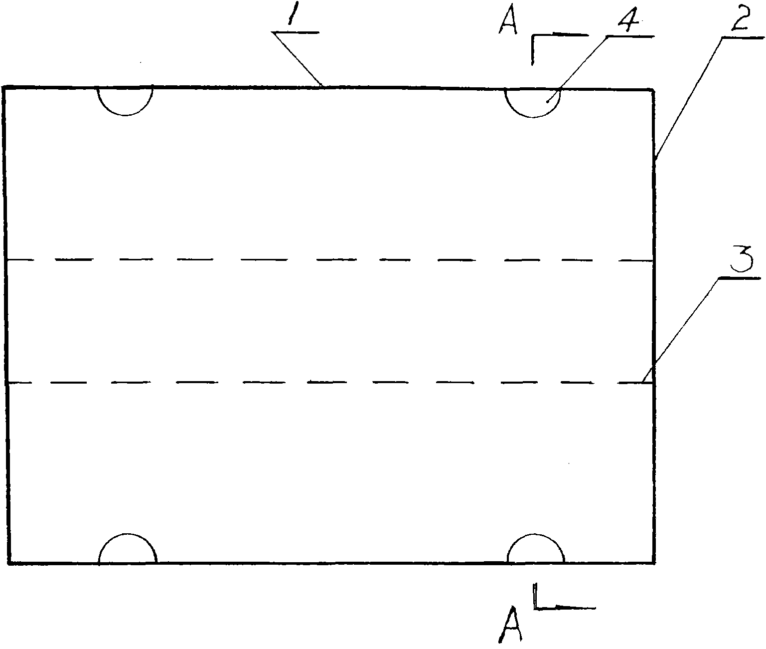
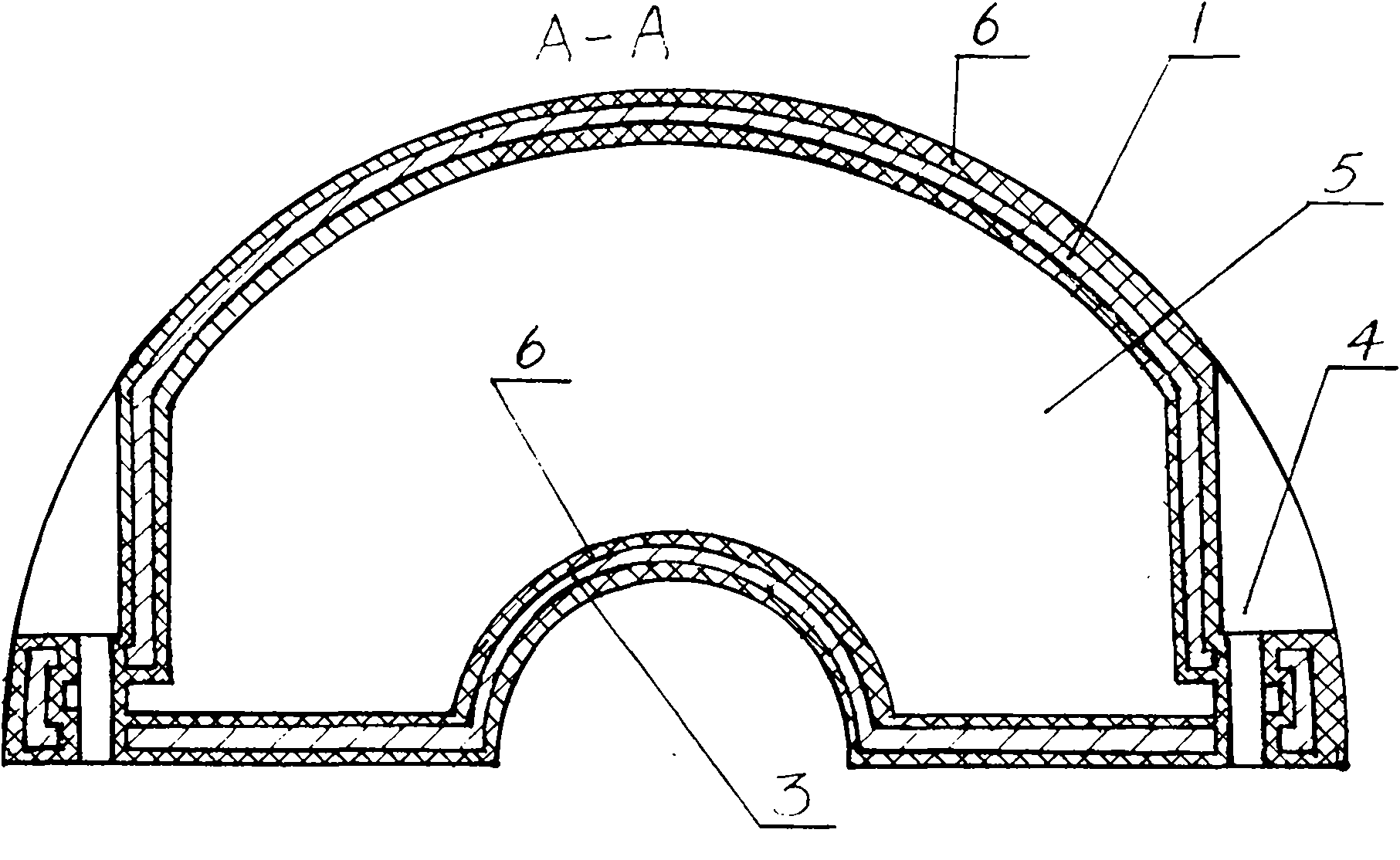
[0019] The mud discharge pipe floating body of embodiment 1 of the present invention (referring to figure 1 , figure 2 ), it is formed by the fastening connection of two semi-tubular floating body bodies through the bolts inserted in the bolt sockets 4. The metal reinforced skeleton layer of each floating body is a semi-tubular hollow structure formed by steel plates through cutting, pressing, welding and other processes. It includes a semi-tubular floating body outer wall layer 1 and 2 semi-circular The end 2 of the floating body, a semi-tubular floating body inner wall layer 3 and a closed cavity 5 in a hollow structure formed by processing them into a whole form an integral metal reinforcement skeleton layer of the floating body. In order to strengthen the corrosion resistance of the metal reinforced skeleton layer and improve the corrosion resistance, the entire surface of the entire metal reinforced skeleton layer is coated with a vulcanized rubber material layer as the...
Embodiment 2
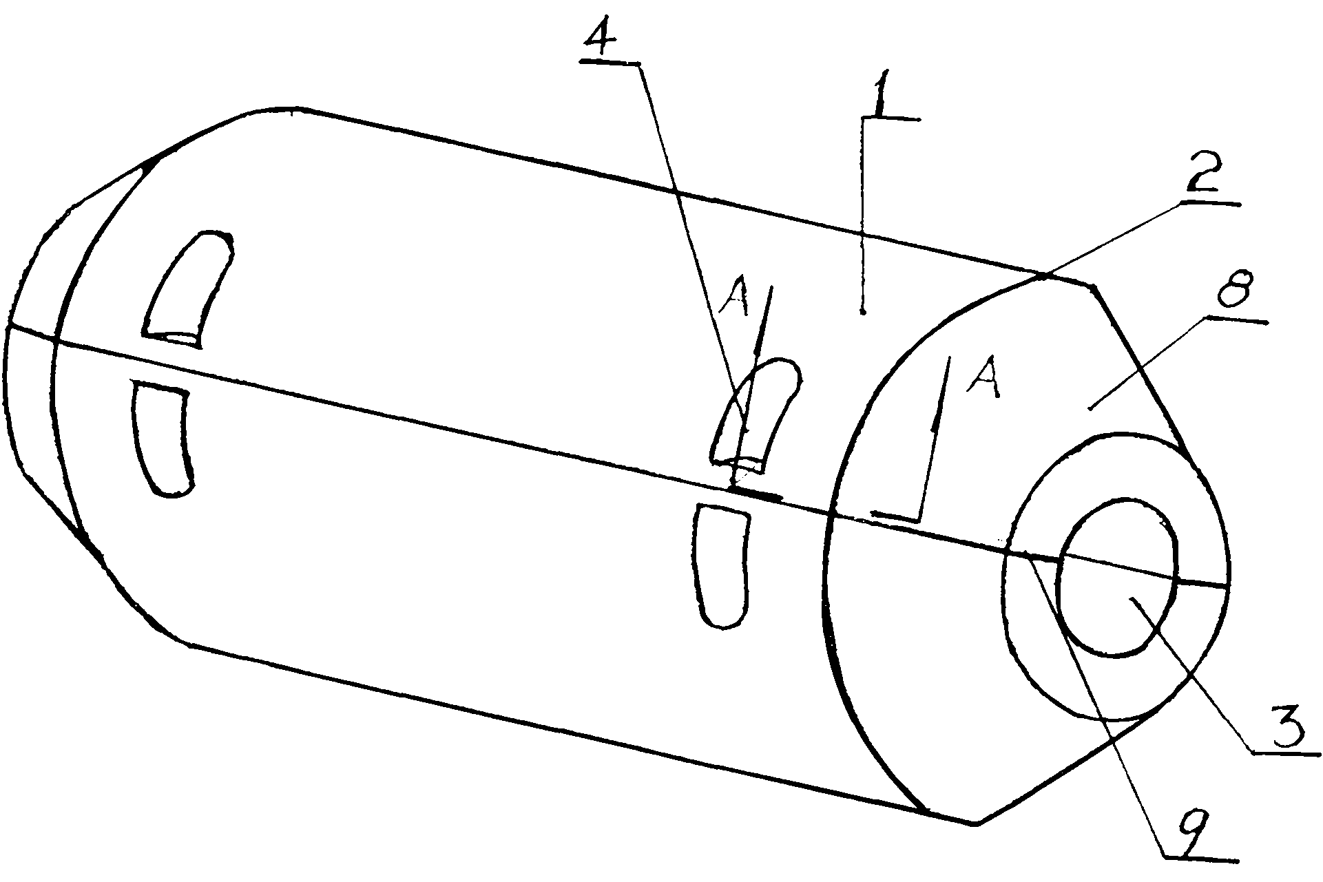
[0022] The mud discharge pipe floating body of embodiment 2 of the present invention (referring to image 3 , Figure 4 ), it is formed by the fastening connection of two semi-tubular floating body bodies through the bolts inserted in the bolt sockets 4. The metal reinforced skeleton layer of each floating body is: the inner wall layer 3 of the semi-tubular floating body and the joint 9 of the floating body are integral structures, and the outer wall layer 1 of the semi-tubular floating body is a frame structure. Two bolts in the transverse section On the semi-circular arc surface of the outer wall layer 1 of the floating body body of the socket 4, an arc-shaped steel plate is set up and welded with the junction of the floating body body 9, instead of the semi-circular arc surface of the bolt socket 4, an interval is set. Curved steel plate structure. The joints of the semi-conical frustum-shaped heads 8 at the ends 2 of the two floating body bodies and the outer wall layer ...
Embodiment 3
[0026] The mud discharge pipe floating body of embodiment 3 of the present invention (referring to Figure 5 , Figure 6), it is because the working environment and conditions are more severe, and the mud discharge pipe is required to have a strong ability to resist wind and waves, anti-collision, long continuous operation time, convenient and quick maintenance in the mud discharge pipeline, especially fast replacement of the mud discharge pipe, etc. A kind of mud discharge pipe floating body designed for a specific requirement. Except that the technical solution described in this embodiment is the same as the technical solution described in Embodiment 1, the other differences mainly include the following points: one is that the metal reinforced skeleton layer of the floating body body is extended along the axis, and at the end of the shaft Part 2 adds an elliptical head 8 (it can also be a hemispherical head, or a spherical head) to further decompose and reduce the impact fo...
PUM
 Abstract
Description
Claims
Application Information
 - R&D
- Intellectual Property
- Life Sciences
- Materials
- Tech Scout
- Unparalleled Data Quality
- Higher Quality Content
- 60% Fewer Hallucinations
Browse by: Latest US Patents, China's latest patents, Technical Efficacy Thesaurus, Application Domain, Technology Topic, Popular Technical Reports.
© 2025 PatSnap. All rights reserved.Legal|Privacy policy|Modern Slavery Act Transparency Statement|Sitemap|About US| Contact US: help@patsnap.com


