Optical fibre fused tapering method using high-frequency pulse carbon dioxide laser as heat source
A technology of carbon dioxide and high-frequency pulses, which is applied in the field of optical fiber, can solve the problems of optical fiber physical damage, unfavorable hot zone range, complex equipment, etc., and achieve the effect of improving utilization rate, easy hot zone range, and reducing energy consumption
- Summary
- Abstract
- Description
- Claims
- Application Information
AI Technical Summary
Problems solved by technology
Method used
Image
Examples
Embodiment 1
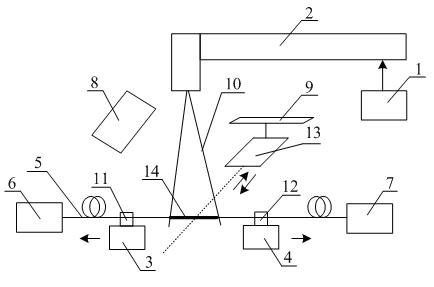
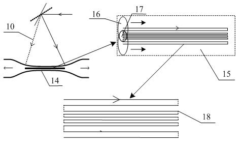
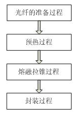
[0025] see figure 1 , figure 2 with image 3 , an optical fiber fusion tapering method using a high-frequency pulsed carbon dioxide laser as a heat source, the operation steps are as follows: 1) the preparation process of the optical fiber, 2) the preheating process, 3) the fusion tapering process, 4) the packaging process; it is characterized in that During the preheating process and the fusion tapering process, a high-frequency pulsed carbon dioxide laser is used as a heat source to heat the bare fiber part of the optical fiber, that is, the laser beam used is a high-frequency pulsed light with a frequency of 5-10 kHz and a duty cycle of 80%±2%, the diameter of the laser spot is 50±5 microns, which is smaller than the diameter of the bare fiber part, which can be approximated as a point heat source. The scanning hot spot of the laser beam in the bare fiber part can be precisely controlled, and only 0.4W laser is needed power can make the bare fiber part reach a molten sta...
Embodiment 2
[0027] This embodiment is basically the same as Embodiment 1, and the special features are as follows:
[0028] , Optical fiber preparation process. Take a standard single-mode optical fiber (5) with a coating layer of 3m in length, remove the coating layer from the middle part with wire strippers, and obtain a bare fiber part (14) with a length of 1cm, and wipe it repeatedly with alcohol The cladding of the bare fiber part (14) is ready for use. Adjust the distance between the two optical fiber clamps (11, 12) to 8cm, place the bare fiber part (14) with the coating removed horizontally at a position perpendicular to the laser beam (10), and place the fiber (5) at one end The optical fiber clamp (11) is clamped firmly, and after a certain weight is applied to make the optical fiber (5) in a naturally stretched state, another optical fiber clamp (12) is clamped. One end of the optical fiber (5) is connected to a 1550nm light source (6), and the other end is connected to an op...
PUM
 Abstract
Description
Claims
Application Information
 - R&D
- Intellectual Property
- Life Sciences
- Materials
- Tech Scout
- Unparalleled Data Quality
- Higher Quality Content
- 60% Fewer Hallucinations
Browse by: Latest US Patents, China's latest patents, Technical Efficacy Thesaurus, Application Domain, Technology Topic, Popular Technical Reports.
© 2025 PatSnap. All rights reserved.Legal|Privacy policy|Modern Slavery Act Transparency Statement|Sitemap|About US| Contact US: help@patsnap.com


