Optical vector-matrix multiplier based on single-waveguide coupling micro-ring resonant cavity

A micro-ring resonant cavity and matrix multiplier technology, applied in the field of optical information processing, can solve the problems of low energy utilization rate, difficult system design and installation, etc., to avoid insertion loss, good optical signal parallelism, and good expansion. sexual effect

Active Publication Date: 2011-08-10
宏芯科技(泉州)有限公司
View PDF3 Cites 11 Cited by
  • Summary
  • Abstract
  • Description
  • Claims
  • Application Information

AI Technical Summary

Problems solved by technology

In addition, due to the propagation and diversity of optical signals in free space, th

Method used


Image

  • Optical vector-matrix multiplier based on single-waveguide coupling micro-ring resonant cavity
  • Optical vector-matrix multiplier based on single-waveguide coupling micro-ring resonant cavity

Examples


Embodiment Construction

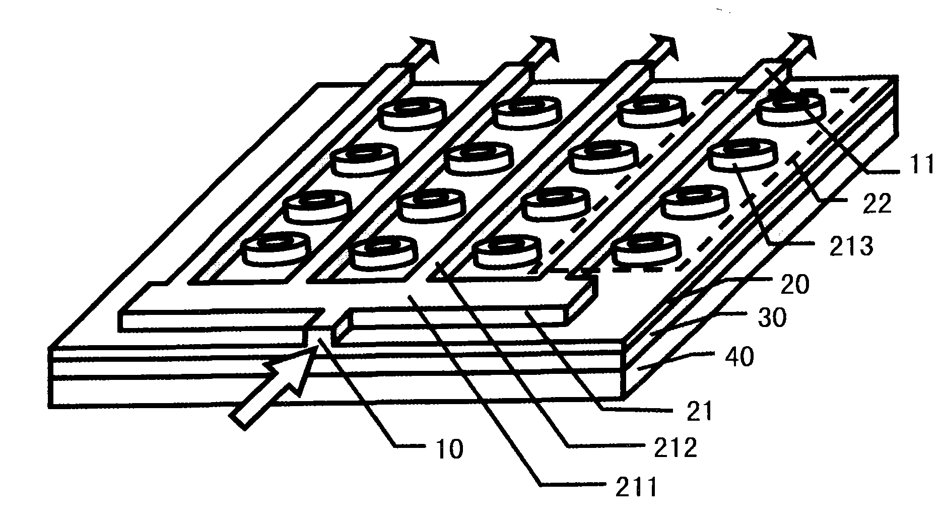
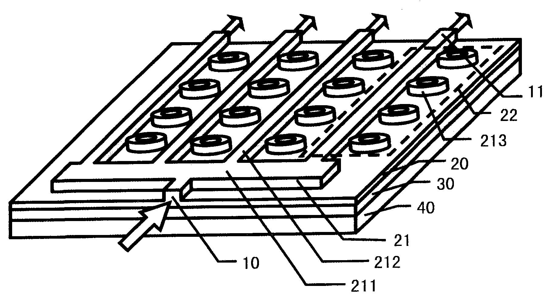
[0026] see figure 1 As shown, the present invention provides an optical vector-matrix multiplier, comprising:

[0027] A substrate 40, the substrate 40 is a silicon substrate;

[0028] A buried layer 30, the buried layer 30 is made on the substrate 40, the material of the buried layer 30 is silicon dioxide, as the cladding of the optical waveguide;

[0029] A top layer 20, the top layer 20 is made on the buried layer 30, the material of the top layer 20 is silicon, a comb structure 21 is etched on the top layer 20, the comb structure 21 includes a back 211 and a tooth portion 212, the comb The shape structure 21 is a beam splitter, and its function is to distribute the input optical signal to the cascaded multi-wavelength modulator 22 corresponding to each tooth of the tooth portion 212 .

[0030] Wherein the middle of the back 211 of the comb structure 21 forms the optical signal input end 10, the optical signal input by the optical signal input end 10 is a multi-wavelength...


PUM


Abstract

The invention discloses an optical vector-matrix multiplier based on a single-waveguide coupling micro-ring resonant cavity, which comprises a substrate, a buried layer and a top layer, wherein the buried layer is manufactured on the substrate; the top layer is manufactured on the buried layer; a comb structure is etched on the top layer; the comb structure comprises a back part and a tooth part; tunable micro-ring resonant cavities are etched in the side direction of the tooth part; each tooth of the tooth part is coupled with the plurality of adjacent tunable micro-ring resonant cavities to form a cascaded multi-wavelength modulator; an input end of an optical signal is formed in the centre of the back part of the comb structure; and an output end of the optical signal is formed at the tail part of the tooth part of the comb structure.

Description

technical field [0001] The invention relates to the technical field of optical information processing, in particular to an optical vector-matrix multiplier. Background technique [0002] Optical vector-matrix multiplier is a widely used optical system in the field of optical signal processing. The earliest optical vector-matrix multiplier model was proposed by J.W.Goodman of Stanford University in the United States, and it is usually called "Stanford vector-matrix multiplier". The optical vector-matrix multiplier mainly includes three parts, namely a light source array, a matrix mask and a detector array. Firstly, using a row of light-emitting diodes as the input vector, arrange the light path between the light-emitting diode array and the matrix mask so that each light-emitting diode only illuminates one column of the matrix mask, and then arrange such light path behind the matrix mask so that the light from the matrix mask The light from each row of the mask is focused o...

Claims


Application Information

Patent Timeline
IPC IPC(8): G06E1/04G02F3/00
Inventor 冀瑞强杨林
Owner 宏芯科技(泉州)有限公司
Why Eureka
Try Eureka