
Polarization and hyper-spectral compression imaging method and system

A compressed imaging and hyperspectral technology, applied in the field of imaging spectrum, can solve problems such as unobtainable, model limitation, and difficulty, and achieve the effect of increasing system luminous flux, reducing data volume, and improving signal-to-noise ratio

Inactive Publication Date: 2011-08-17
SUZHOU UNIV
View PDF2 Cites 7 Cited by
  • Summary
  • Abstract
  • Description
  • Claims
  • Application Information

AI Technical Summary

Problems solved by technology

In this type of method, the improvement of hyperspectral compression imaging performance needs to be guaranteed by a high-fidelity data solution method. The previously reported method is based on a single nonlinear diffraction device (prism), which is limited by the system model. limited fidelity
[0004] To sum up, the existing technology has the following defects: (1) It cannot realize instantaneous shooting of large field of view targets, and the huge amount of data collected by push-broom imaging poses a huge challenge to the existing data storage and transmission capabilities
(2) Ordinary hyperspectral imaging technology relies on slits to limit the field of view, and cannot obtain high luminous flux and even signal-to-noise ratio under the condition of high resolution. It is particularly difficult to image targets with weak light intensity and strong scattering, and is not suitable for biological Applications such as tissue imaging
(3) The current spatially encoded hyperspectral compression imaging method relies on a single nonlinear dispersion element, and is limited by the model, making it difficult to obtain high-fidelity data solution methods

Method used


Image

  • Polarization and hyper-spectral compression imaging method and system
  • Polarization and hyper-spectral compression imaging method and system
  • Polarization and hyper-spectral compression imaging method and system

Examples


Embodiment 1

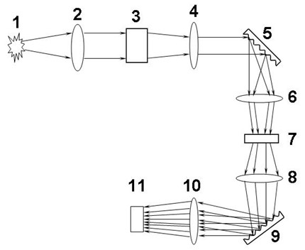
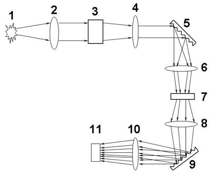
[0022] Embodiment one: see figure 1 As shown, a polarization-hyperspectral compression imaging system is sequentially provided with an objective lens 2, a polarization modulator 3, a collimating mirror 4, a first linear dispersion device 5, a first convex lens 6, and a spatial modulation mask along the direction of light transmission. A template 7, a second convex lens 8, a second linear dispersion device 9, a lens 10 and an area array detector 11, the objective lens makes the object image on the polarization modulator.

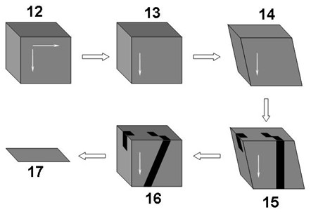
[0023] The polarization-hyperspectral compression imaging system is placed at a proper position directly in front of the target object 1, and the focusing work before imaging is completed. Objects within a certain field of view within the target object 1 are imaged on the polarization modulator 3 via the objective lens 2 . The polarization modulator implements polarization modulation on the incident optical signal, selects a certain polarization state to exi...


PUM


Abstract

The invention discloses a polarization and hyper-spectral compression imaging method and system. The polarization and hyper-spectral compression imaging system is provided with an objective lens, a polarization modulator, a collimating lens, a first linear dispersion device, a first convex lens, a spatial modulation mask plate, a second convex lens, a second linear dispersion device, a lens and adetector in sequence along the direction of light transmission, wherein the objective lens is used for imaging a target on the polarization modulator. The polarization and hyper-spectral compression imaging method comprises the following steps: imaging the target on the polarization modulator, collimating the emergent light, carrying out first dispersion on the collimated emergent light, carryingout spatial modulation on the dispersed light signal, carrying out second dispersion, projecting the light on the detector, collecting data by using a computer, completing data calculation, and restoring four-dimensional data information of the target. The invention realizes the hyper-spectral instantaneous compression imaging of three-dimensional data cubes in a certain vision field under the control of polarization modulation, greatly reduces the quantity of data received by the detector, improves the signal-to-noise ratio of the system and is especially beneficial to the target imaging of weak light intensity and strong dispersion.

Description

technical field [0001] The invention relates to an imaging spectrum technology, in particular to a method combining polarization technology and hyperspectral compression imaging technology, and a system for realizing the method. Background technique [0002] Since the 1980s, hyperspectral imaging technology has been widely used in atmospheric monitoring, resource surveying, forest protection, medical diagnosis and other fields. Traditional hyperspectral imagers need to use slits to limit the field of view, and the incident light flux is determined by the width of the slit. Increasing the slit width will reduce the spectral resolution of the spectral imager. For scenes with weak light intensity and strong scattering, it is impossible to obtain high signal-to-noise ratio images while ensuring high resolution. The large number of 3D data cubes obtained by push broom brings difficulties to real-time processing and ground transmission. The problem of data volume has become an im...

Claims


Application Information

Patent Timeline
IPC IPC(8): G01J3/447G01J3/02
Inventor 陈宇恒周建康陈新华季轶群沈为民
Owner SUZHOU UNIV
Learn More