Transient temperature distribution sensor in fuel cell

A fuel cell and internal temperature technology, which is applied to fuel cell components, fuel cell additives, fuel cell heat exchange, etc., can solve the problem of not reflecting the temperature distribution of fuel cells, not meeting the requirements of real-time temperature measurement, and the scope of use Limitation and other issues, to achieve the effect of simple structure, convenient and quick disassembly, and small heat capacity

Active Publication Date: 2011-08-17
BEIJING UNIV OF TECH
View PDF3 Cites 18 Cited by
  • Summary
  • Abstract
  • Description
  • Claims
  • Application Information

AI Technical Summary

Problems solved by technology

It is relatively easy to measure the temperature of the outer surface of the fuel cell by this method, but in order to obtain the real temperature distribution inside the fuel cell, it is necessary to change the structure of the cell and use special materials that can transmit infrared radiation to make the end plate of the fuel cell, etc. The processing is complicated, and the temperature measurement is inaccurate, especially in the case of water droplets inside the fuel cell, and it cannot reflect the real temperature distribution inside the fuel cell, and the formation of water droplets inside the fuel cell is a problem in most working conditions. phenomenon, so the scope of application of this method is limited
[0003] Common temperature measurement methods include thermosensitive paint method, coloring method, etc., but these methods cannot meet the requirements of real-time temperature measurement. For the special structure of fuel cells, the use of these methods is also limited

Method used


Image

  • Transient temperature distribution sensor in fuel cell
  • Transient temperature distribution sensor in fuel cell
  • Transient temperature distribution sensor in fuel cell

Examples


Embodiment Construction

[0030] Accompanying drawing is the specific embodiment of the present invention;

[0031] Below in conjunction with accompanying drawing, content of the present invention is described in further detail:

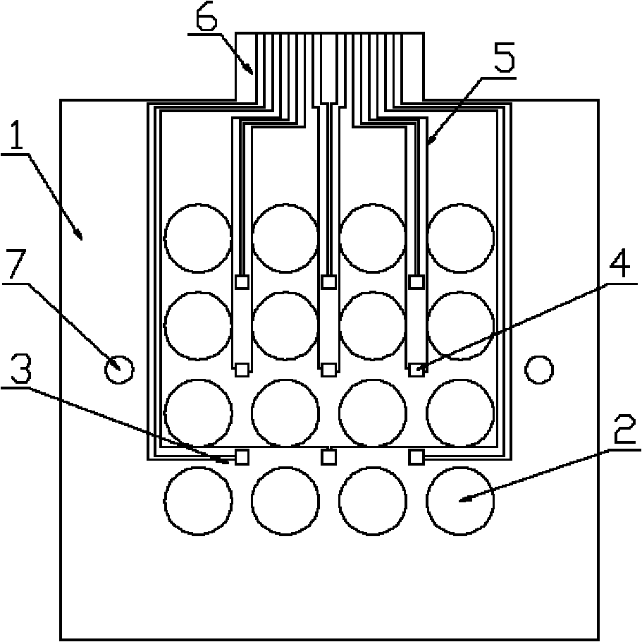
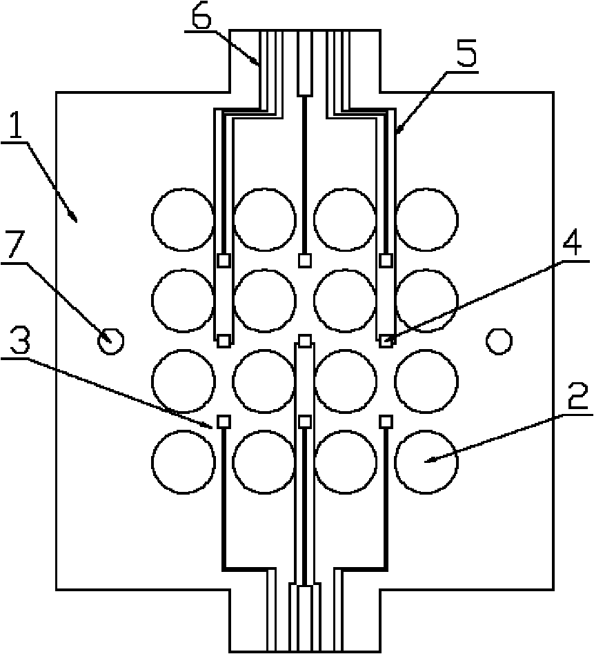
[0032] refer to figure 1 , figure 2 , image 3 As shown, the present invention includes that some thin-film thermocouples 4 are coated on the ribs 3 between two adjacent flow channels 2 on the graphite flow field plate 1 in the fuel cell, and the lead-out wires 5 of the thin-film thermocouples 4 extend to the graphite flow field The edge of the board 1 is provided with a standard wiring port 6 connected to an external circuit at the end of the lead wire 5 . The thin-film thermocouple 4 and its lead wire 5 of the present invention are all made on the graphite flow field plate 1, and the lead wire 5 extends to the end of the graphite flow field plate 1 with a width of 0.05-0.1 mm and a thickness of no more than 0.2 μm. Through the standard data interface 6 connected to the...


PUM

PropertyMeasurementUnit
thicknessaaaaaaaaaa
thicknessaaaaaaaaaa
thicknessaaaaaaaaaa

Abstract

The invention discloses a transient temperature distribution sensor in a fuel cell, and thin film thermocouples are arranged on ribs between adjacent flow passages on a graphite flow field plate of the fuel cell for measuring transient temperature distribution in the fuel cell. The single thin film thermocouple is formed by adopting a vacuum evaporation coating technology for evaporation of four layers of thin films, a silicon dioxide insulating layer with the thickness of 0.1-0.15 mu m is plated at the first layer, copper is plated at the second layer, nickel is plated at the third layer, the thicknesses of the copper plated layer and the nickel plated layer are 0.08-0.1 mu m respectively, and a silicon dioxide thin layer with the thickness of 0.01-0.02 mu m is finally plated. Leading-out wires of the thin film thermocouples extend to the edge of the graphite flow field plate by utilizing the process of a printed circuit, a standard wiring port for connecting with an external circuitis further arranged, and a data acquisition system is used for exporting signals. A measuring device is simple and easy to operate, the real-time temperature distribution in the fuel cell is measured, the cell is easy to disassemble and assemble, and the impacts on the overall performances of the fuel cell are small.

Description

technical field [0001] The invention belongs to a transient temperature distribution sensor inside a fuel cell, and relates to the measurement of the transient temperature distribution inside the fuel cell, in particular to a method for measuring the transient temperature. Background technique [0002] Due to the structure of the fuel cell itself, it is difficult to measure the transient temperature distribution inside it. Most of the previous temperature measurement methods are to implant tiny temperature sensors or thermocouples into the flow channel of the fuel cell, or to heat press it into the diffusion layer of the cell. and catalytic layer, but these methods seriously deteriorate the performance of the fuel cell. In addition, the fuel cell temperature measurement method also includes infrared radiation thermometry. Since the propagation speed of infrared radiation is the speed of light, the response time of temperature measurement is short, and the temperature of the ...

Claims


Application Information

Patent Timeline
Patent Type & Authority Applications(China)
IPC IPC(8): H01M8/02G01K7/02H01M8/04007
CPCY02E60/50
Inventor 郭航聂志华叶芳马重芳
Owner BEIJING UNIV OF TECH
Why Eureka
Try Eureka