Plasma display panel

A display panel and plasma technology, which is applied to AC plasma display panels, tube structural parts, discharge tubes, etc., can solve the problems of inability to reduce discharge voltage, deterioration of sputtering resistance, and deterioration of image quality.

Inactive Publication Date: 2011-08-17
PANASONIC CORP
View PDF6 Cites 0 Cited by
  • Summary
  • Abstract
  • Description
  • Claims
  • Application Information

AI Technical Summary

Problems solved by technology

However, there are problems in that the discharge voltage becomes higher, the "discharge delay" becomes larger, and image quality degradation such as lighting failure occurs.
[0014] In addition, in protective layers other than MgO, there is also a problem that sputtering resistance deteriorates due to ion impact during discharge.
On the other hand, in the case of forming MgO crystal particles on the MgO protective layer, although the "discharge delay" and lighting failure can be reduced, there is a problem that the discharge voltage cannot be reduced.

Method used


Image

  • Plasma display panel
  • Plasma display panel
  • Plasma display panel

Examples


Embodiment approach

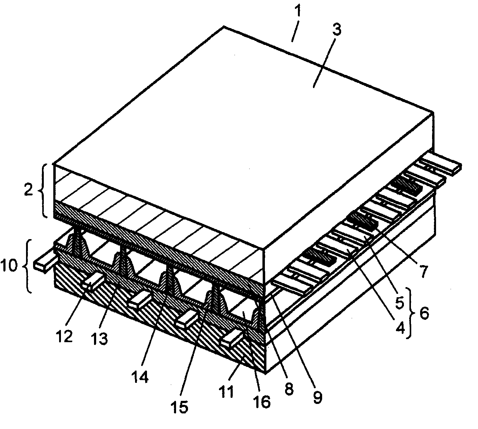
[0035] figure 1 It is a perspective view showing the structure of PDP1 in the embodiment of the present invention. The basic structure of the PDP 1 is the same as that of a normal AC surface discharge type PDP. Such as figure 1 As shown, for PDP1, the first substrate (hereinafter referred to as "front panel 2") composed of front glass substrate 3, etc., and the second substrate (hereinafter referred to as "rear panel 10") composed of rear glass substrate 11, etc. ”) are arranged facing each other, and the outer peripheral portion of the PDP 1 is hermetically sealed by a sealing member made of glass frit or the like. Discharge gas such as xenon (Xe) and neon (Ne) is sealed in discharge space 16 inside the sealed PDP 1 at a pressure of 400 Torr to 600 Torr (53300 Pa to 80000 Pa).

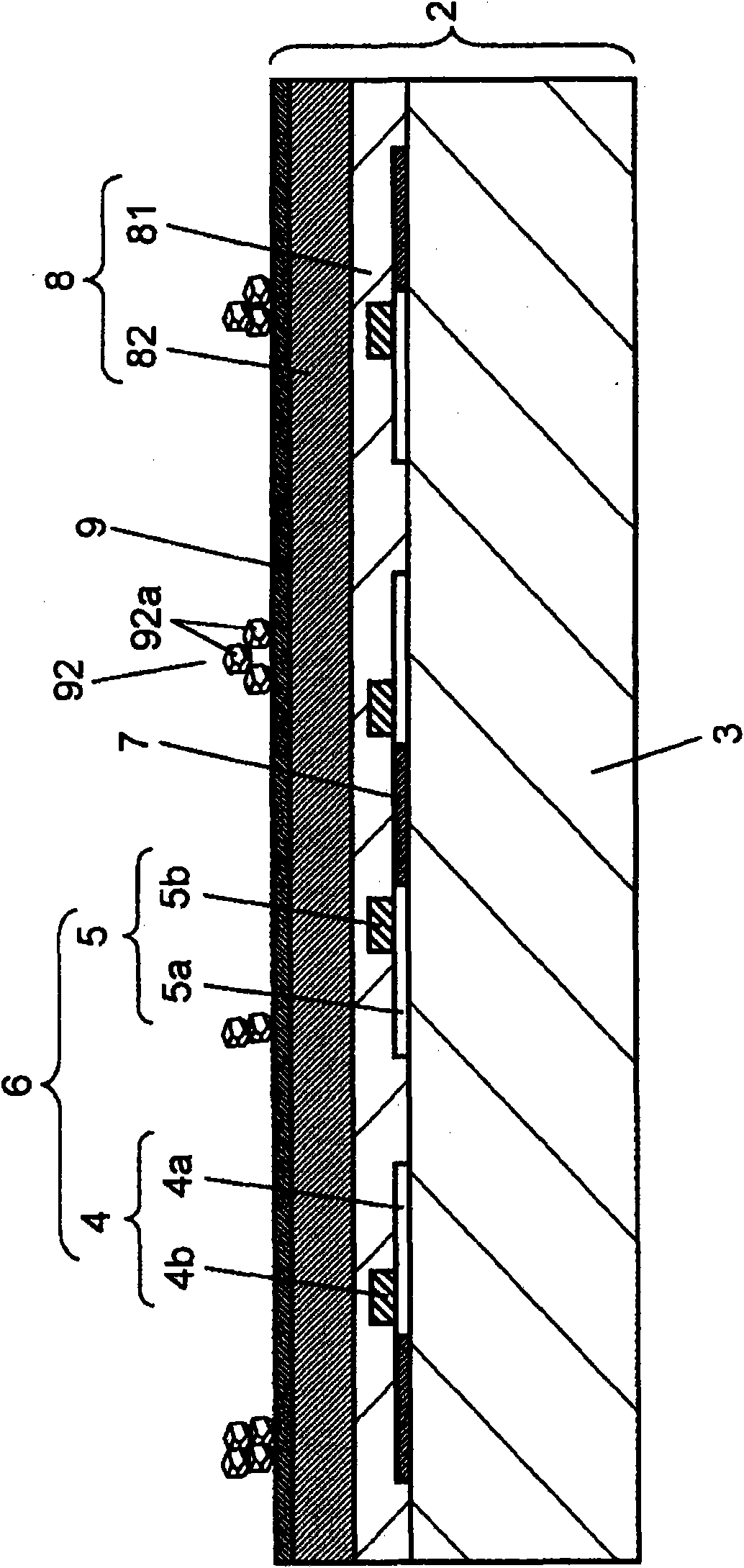
[0036] On the front glass substrate 3 of the front panel 2, a plurality of strip-shaped display electrodes 6 composed of scan electrodes 4 and sustain electrodes 5 and black stripes (light shieldin...


PUM


Abstract

Realized is a plasma display panel having high definition and high-luminance display capabilities and low power consumption. To this end, the PDP is provided with a front plate (2), wherein a dielectric layer (8) is formed to cover display electrodes (6) formed on a front glass substrate (3) and wherein a protective layer (9) is also formed on the dielectric layer (8), and a back plate which is placed to face the front plate (2) to form a discharge space filled with a discharge gas between. On the back plate, address electrodes are formed in a direction to cross the display electrodes (6), and partition walls that divide the discharge space are also provided. Furthermore, the protective layer (9) is formed from a metal oxide comprising magnesium oxide and calcium oxide, and also contains zinc. In addition, the angle of diffraction generated by the peak of the metal oxide is between the angle of diffraction generated by the peak of the magnesium oxide and the angle of diffraction generated by the peak of the calcium oxide, with X-ray diffraction analysis at the surface of the protective layer (9).

Description

technical field [0001] The present invention relates to a plasma display panel used in display devices and the like. Background technique [0002] Plasma display panels (hereinafter referred to as "PDPs") are commercialized as 100-inch-class televisions and the like because they can achieve high definition and large screen sizes. In recent years, the application of PDP to high-definition televisions, which have more than twice the number of scanning lines compared with the conventional NTSC system, is progressing. In addition, there are increasing demands for further reduction of power consumption in response to energy issues, and demands for lead-free PDPs in response to environmental issues. [0003] A PDP basically consists of a front panel and a rear panel. The front panel is composed of the following parts: a glass substrate of sodium borosilicate glass manufactured by the floating method, a display electrode composed of stripe-shaped transparent electrodes and bus el...

Claims


Application Information

Patent Timeline
Patent Type & Authority Applications(China)
IPC IPC(8): H01J11/02H01J11/12H01J11/22H01J11/24H01J11/26H01J11/34H01J11/40
CPCH01J11/40H01J11/12
Inventor 桥本润后藤真志越后纪康
Owner PANASONIC CORP
Why Eureka
Try Eureka