
Spaceborne calibration light source LED (light emitting diode) light emitting performance testing device

A technology of luminous performance and on-board calibration, applied in the field of space optics

Inactive Publication Date: 2011-08-24
CHANGCHUN INST OF OPTICS FINE MECHANICS & PHYSICS CHINESE ACAD OF SCI
View PDF4 Cites 10 Cited by
  • Summary
  • Abstract
  • Description
  • Claims
  • Application Information

AI Technical Summary

Problems solved by technology

[0003] In order to solve the problem that the existing on-star calibration light source LED luminous performance detection device can only detect the light performance of a single LED, the present invention provides an on-star calibration light source LED luminous performance test device

Method used


Image

  • Spaceborne calibration light source LED (light emitting diode) light emitting performance testing device
  • Spaceborne calibration light source LED (light emitting diode) light emitting performance testing device
  • Spaceborne calibration light source LED (light emitting diode) light emitting performance testing device

Examples


specific Embodiment approach 1

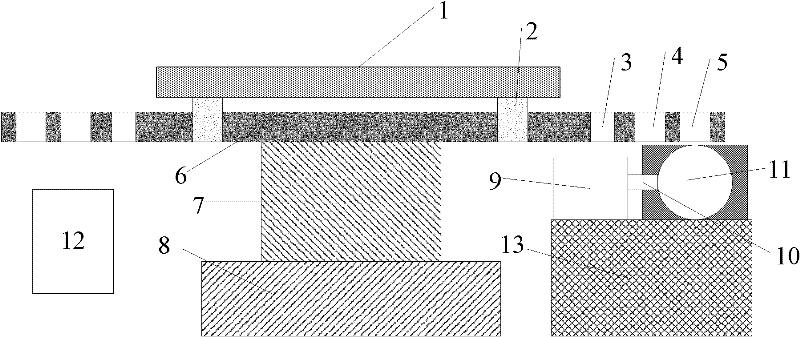
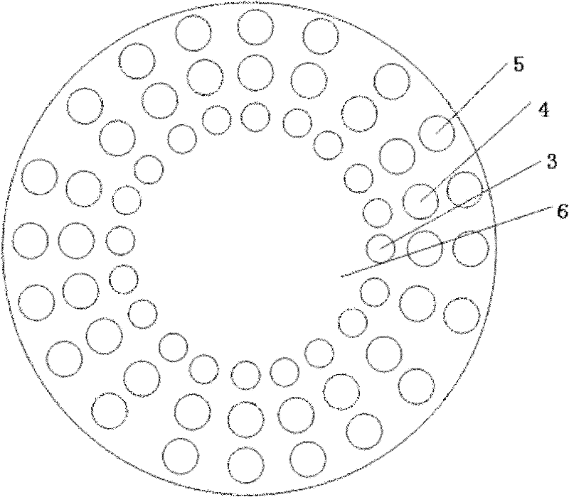
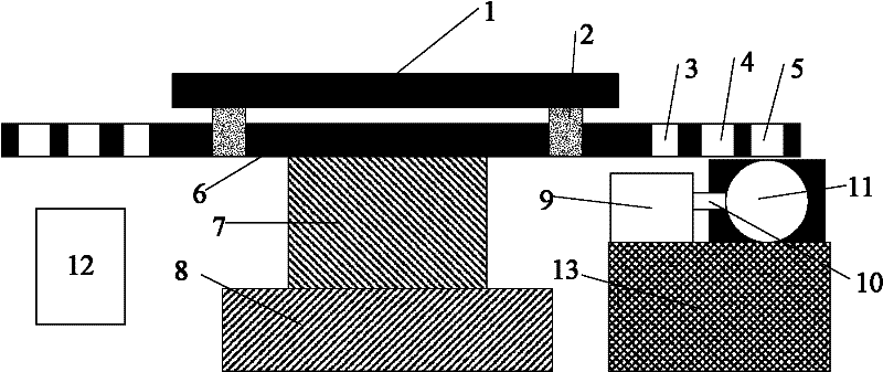
[0010] Specific implementation mode 1. Combination figure 1 and figure 2 Describe this embodiment, the on-board calibration light source LED luminous performance test device, the device includes an LED drive circuit 1, a mounting bracket 2, a rotating disc 6, a rotating disc drive system 7, a fixed bracket 8, a spectrometer 9, an optical fiber 10, Integrating sphere 11, computer control system 12; described LED driving circuit 1 and rotating disk 6 are respectively fixed on the installation bracket 2, and LED testing installation hole is set on rotating disk 6, and integrating sphere 11 is arranged at the corresponding position of LED testing installation hole , the light exit hole of the integrating sphere 11 is connected to one end of the optical fiber 10, and the other end of the optical fiber 10 is connected to the spectrometer 9; the rotating disk drive system 7 is fixed at the bottom of the rotating disk 6, and the rotating disk driving system 7 is fixed on the fixed br...

specific Embodiment approach 2

[0015] Specific implementation mode 2. This implementation mode is an application example of the on-board calibration light source LED luminous performance test device described in specific implementation mode 1:

[0016] combine figure 1 , the LED driving circuit 1 is an LED constant current driving board, and its driving current is 5mA, 10mA, 15mA, 20mA, 25mA, 30mA, 35mA, 40mA, 45mA, 50mA, 60mA, 85mA, 100mA; For the required current, each LED is powered by a constant current. combine figure 2 , the first LED test installation hole 3, the second LED test installation hole 4 and the third LED test installation hole 5 can be respectively installed Test mounting holes for cannonball LEDs and SMD LEDs for testing different shapes of LEDs. The rotating disc 6 is a rotatable disc with a diameter of 0.5m, and the LEDs to be tested are installed in the corresponding test installation holes, and the corresponding LEDs can only be installed in the same ring of installation holes f...


PUM

PropertyMeasurementUnit
Diameteraaaaaaaaaa

Abstract

The invention discloses an spaceborne calibration light source LED (light emitting diode) light emitting performance testing device, relates to the field of space optics, and solves the problem that the traditional spaceborne calibration light source LED light emitting performance testing device only can detect the optical performance of a single LED. The testing device comprises an LED driving circuit, a mounting bracket, a rotary disc, a rotary disc driving system, a fixed support, a spectrograph, an optical fiber, an integration sphere and a computer control system; the LED driving circuit and the rotary disc are fixed on the mounting bracket; the rotary disc is provided with an LED testing and mounting hole; the integration sphere is arranged at the corresponding position of the LED testing and mounting hole; a light emergent hole of the integration sphere is connected with one end of the optical fiber, and the other end of the optical fiber is connected with the spectrograph; the rotary disc driving system is arranged at the bottom of the rotary disc and fixed to the fixed support; and the computer control system is respectively connected with the rotary disc driving system and the spectrograph. The testing device provided by the invention is applied to the spaceborne calibration light source LED screening and testing of a space camera.

Description

technical field [0001] The invention relates to the field of space optics, in particular to a light performance testing device for a calibration light source LED on a space camera. Background technique [0002] In the light-emitting diode LED upgrade screening test for on-board calibration light sources of space cameras, the luminous performance of LEDs is an important indicator for screening LEDs. Only LEDs that pass the strict screening test can be used as on-board calibration light sources for space cameras. LED screening tests include: high temperature storage, temperature shock, electrical aging and other tests. After each test, the luminous performance of the LED must be tested, mainly to detect the emission spectrum of the LED. The peak wavelength and half-wave width of the LED can be calculated through the emission spectrum. , if the system is calibrated, parameters such as the radiation intensity or radiation power of the LED can be calculated. At present, there ar...

Claims


Application Information

Patent Timeline
IPC IPC(8): G01M11/02G01J3/28
Inventor 李宪圣任建伟任建岳万志刘则洵全先荣叶钊
Owner CHANGCHUN INST OF OPTICS FINE MECHANICS & PHYSICS CHINESE ACAD OF SCI
Learn More