Method for preparing micropore array fiber bragg grating

A fiber grating, micro-hole array technology, applied in the direction of cladding fiber, optical waveguide light guide, etc., can solve the problems of weakening the mechanical strength, increasing the sensitivity, and failing to reflect the selective corrosion of the type II damage zone.

Inactive Publication Date: 2011-08-24
JILIN UNIV
View PDF2 Cites 21 Cited by
  • Summary
  • Abstract
  • Description
  • Claims
  • Application Information

AI Technical Summary

Problems solved by technology

If the high-temperature-resistant fiber grating is chemically etched to increase its sensitivity to environmental changes, the overall fiber grating will also become thinner and weaken its mechanical strength, which does not reflect the advantages of selective corrosion in the type II damage zone.
[0004] It can be seen that how to prepare a fiber grating that is resistant to high temperature and sensitive to the refractive index of the environment and can maintain a certain mechanical strength poses certain challenges to the preparation and processing of the grating.

Method used


Image

  • Method for preparing micropore array fiber bragg grating
  • Method for preparing micropore array fiber bragg grating
  • Method for preparing micropore array fiber bragg grating

Examples


Embodiment 1

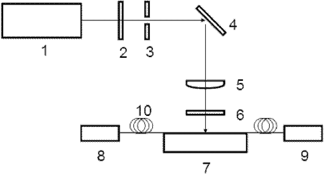
[0028] Infrared femtosecond laser combined with phase mask method (preparation method refers to "Formation of Type I-IR and Type II-IR gratings with an ultrafast IR laser and a phase mask", Christopher W.Smelser, Optics Express, 2005, 13, 5377 -5386) A type II Bragg fiber grating with a damage zone extending from the core to the outer edge of the cladding was prepared in a single-mode fiber for communication (SMF-28e). Preparation device such as figure 1 As shown, the laser light source 1 used in this embodiment is a titanium-doped sapphire femtosecond pulse laser manufactured by Spectra-Physics Corporation of the United States, with an operating wavelength of 800 nm and a repetition rate of 1 kHz. The attenuator 2 is adjusted so that the incident single pulse energy is 0.87 mJ. The femtosecond laser pulse passes through the shutter 3, is reflected by the total reflection mirror 4, is focused by the cylindrical lens 5 with a focal length of 40 mm, and passes through the phase ...

Embodiment 2

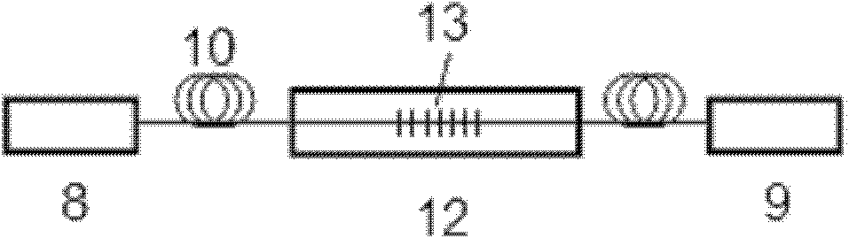
[0030] Utilize the method described in embodiment 1 to prepare a section of Bragg fiber grating 13, it is fixed on image 3In the shown plastic container 12 for fiber grating etching, hydrofluoric acid is sealed in the container. The optical fiber 10 connected to both ends of the Bragg fiber grating is respectively connected to a light source 8 and a spectrum analyzer 9 to monitor the spectral changes during the corrosion process of the fiber Bragg grating. In this embodiment, hydrofluoric acid with a volume concentration of 4% is used to etch the grating at room temperature (20° C.). After about 40 minutes of corrosion, it can be seen from the spectrum analyzer that the resonance peak of the transmission spectrum of the Bragg fiber grating has moved to the short wave direction obviously. At this time, take out the fiber grating, stop the corrosion, and rinse it with saturated sodium bicarbonate solution to neutralize the residual hydrofluoric acid, and then put it into an ul...

Embodiment 3

[0032] Using the method described in Example 1 and Example 2, a section of microhole array type Bragg fiber grating was prepared, and its environmental refractive index, stress response test and high temperature annealing research were carried out. Figure 6 The variation of the central wavelength of the microhole array Bragg fiber grating under different environmental refractive indices is given. The points in the figure represent the experimental results, and the curve is the fitting of the experimental data. The first point represents the device in air (refractive index 1), and the other points represent the device in the refractive index matching liquid. The matching liquid is made of glycerin and water in different volume ratios, and its refractive index is calibrated by an Abbe refractometer. From the results shown in the figure, it can be seen that the Bragg resonance peak moves to the long-wavelength direction with the increase of the environmental refractive index, an...


PUM


Abstract

The invention discloses a method for preparing a micropore array fiber bragg grating, belongs to the technical field of fiber bragg grating sensors and particularly relates to a method for preparing the micropore array fiber bragg grating by combining laser processing with a chemical corrosion technology. The method comprises the following steps of: producing a section of fiber bragg grating of which a damage zone extends to the outer edge of a coating from a fiber core on an optical fiber by a focusing laser beam with power of 0.5 to 1.5W; carrying out chemical corrosion on the section of fiber bragg grating at the temperature of between 10 and 50 DEG C by using 1 to 40 volume percent hydrofluoric acid; and carrying out neutralization by using alkaline solution and carrying out ultrasonic cleaning by using deionized water so as to obtain a micropore array fiber bragg grating structure of which the grating damage zone extends to the fiber core from the outer edge of the coating. By the method, the grating zone extends to the surface of the optical fiber from the inside of the optical fiber and the corroding process is mainly carried out along the damaged grating zone, so that the corroded structure has high mechanical strength, the sensing sensitivity is improved and the micropore array fiber bragg grating has high temperature stability.

Description

technical field [0001] The invention belongs to the technical field of optical fiber grating sensors, and in particular relates to a method for preparing microhole array type optical fiber gratings by using laser processing combined with chemical corrosion technology. Background technique [0002] A fiber grating is an all-fiber passive device that reflects or loses some specific wavelengths formed by periodically modulating the refractive index in the fiber along the axial direction. As a sensitive element with excellent performance, fiber Bragg grating can sense various physical, chemical and biological parameters, including temperature, stress, refractive index and so on. Because it is free from electromagnetic interference, resistant to high temperature and high pressure, can work in harsh environments such as corrosive, flammable and explosive, and is small in size, high in sensitivity, compatible with optical fiber systems, and easy to network for distributed sensing, ...

Claims


Application Information

Patent Timeline
Patent Type & Authority Applications(China)
IPC IPC(8): G02B6/02
Inventor 于永森孙洪波杨睿陈超陈歧岱
Owner JILIN UNIV
Why Eureka
Try Eureka