Three-dimensional hierarchical air supply combined waste incinerator

An incineration device and waste technology, applied in the direction of incinerators, combustion methods, combustion types, etc., can solve the problems of narrow application range and single function, and achieve the reduction of excess air coefficient, control of combustion temperature and oxygen content, and reduction of fly ash Take away the effect of loss

Inactive Publication Date: 2011-08-31
HARBIN INST OF TECH
View PDF7 Cites 13 Cited by
  • Summary
  • Abstract
  • Description
  • Claims
  • Application Information

AI Technical Summary

Problems solved by technology

[0009] In order to solve the problems of single function and narrow application range in the existing waste incineration devices, the present invention further provides a three-dimensional graded air supply combined waste incineration device

Method used


Image

  • Three-dimensional hierarchical air supply combined waste incinerator
  • Three-dimensional hierarchical air supply combined waste incinerator
  • Three-dimensional hierarchical air supply combined waste incinerator

Examples


specific Embodiment approach 1

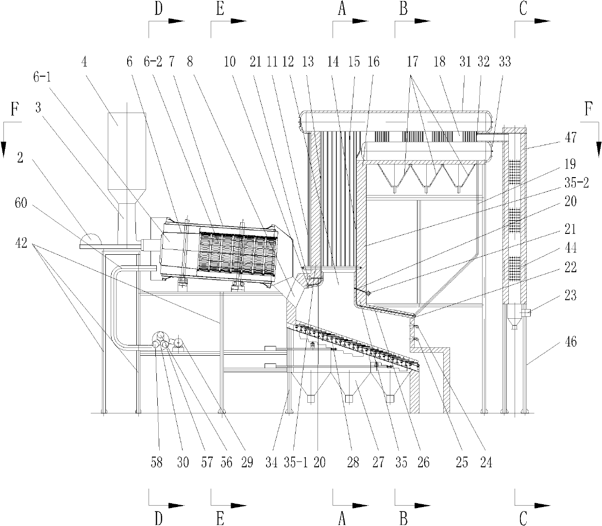
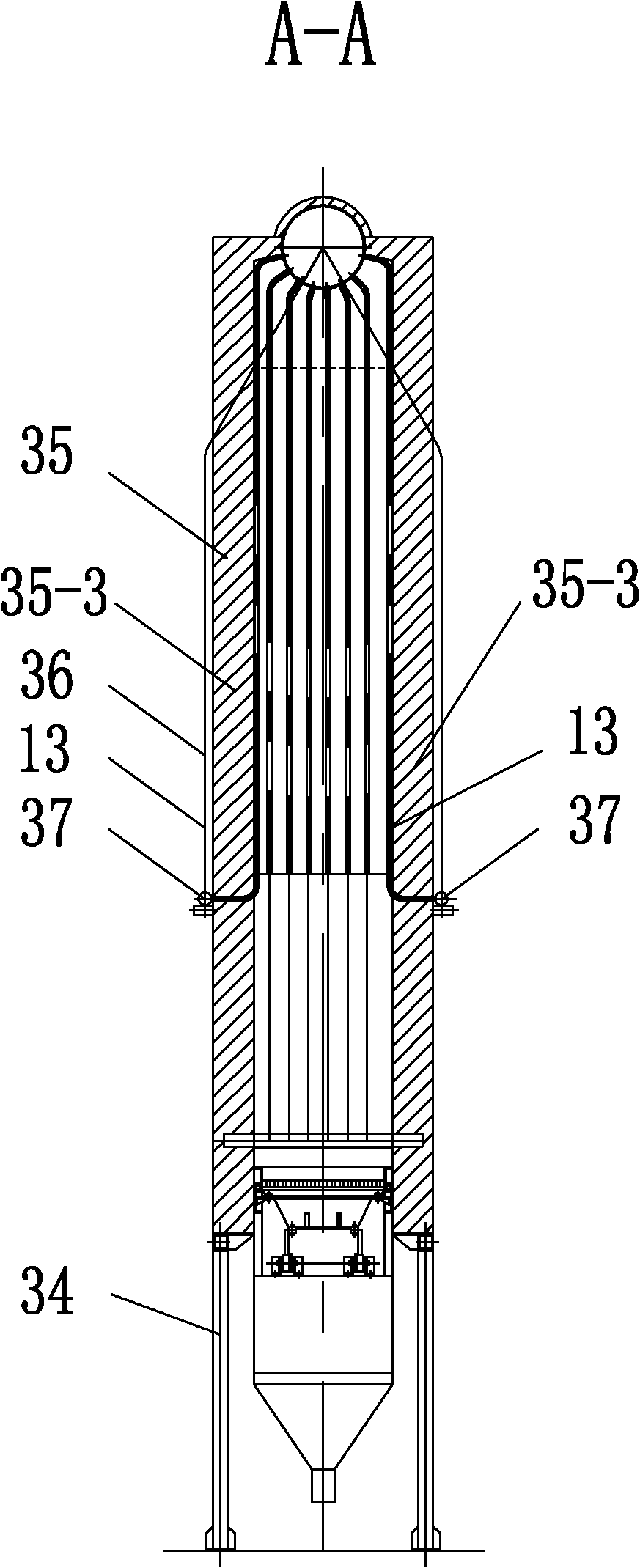
[0020] Specific implementation mode one: combine Figure 1-7 Description, the three-dimensional graded air supply combined waste incineration device of the present embodiment consists of a feeding device 3, a rotary drying and pyrolysis device 7, a first support 42, a grate type incineration device 16, a pyrolysis gas conveying fan 29, a thermal Decomposition gas distribution device 30 and a plurality of pipelines 60, one end of the rotary dry pyrolysis device 7 is provided with a feed port 38, an oil combustion nozzle 39, an air inlet 40 and a lye nozzle 41, the upper The lower end of the feeding device 3 communicates with the feed port 38 of the rotary drying pyrolysis device 7, and the other end of the rotary drying pyrolysis device 7 communicates with the grate type incineration device 16, and the feeding device 3 and the rotary drying heat The solution device 7 is all fixedly installed on the first support 42;

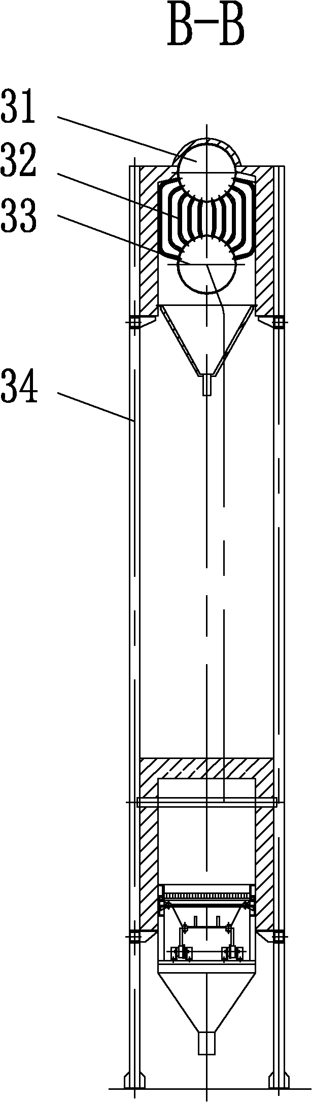
[0021] The grate type incineration device 16 includes a gra...

specific Embodiment approach 2

[0024] Specific implementation mode two: combination figure 1 and Figure 6 Explain that the rotary drying and pyrolysis device 7 described in this embodiment is composed of a transmission device 51, an outer cylinder 53, an inner cylinder 6, an insulating layer 50, and an outer shell 52, and the inner cylinder 6 is located in the outer cylinder 53 And the two ends of the inner cylinder 6 are installed on the side walls of the two ends of the outer cylinder 53, the inner cylinder 6 and the outer cylinder 53 are arranged coaxially, and the outer walls of the outer cylinder 53 are wrapped with an insulating layer 50, An outer shell 52 is set on the outer wall of the insulation layer 50, the inner cylinder 6 is composed of a front cylinder 6-1 and a rear cylinder 6-2, and the rear cylinder 6-2 is uniformly processed with The grate hole 49, the front cylinder body 6-1 is provided with a feed inlet 38, a fuel combustion nozzle 39 and a lye nozzle 41, and the transmission device 51...

specific Embodiment approach 3

[0025] Specific implementation mode three: combination figure 1 Explanation, in this embodiment, the feeding device 3 in this embodiment is composed of a hopper 4 and a pusher 2 , the pusher 2 is located at the lower end of the hopper 4 and the pusher 2 is connected to a rotary drying and pyrolysis device 7 . With such a design, the waste can be pushed into the rotary drying and pyrolysis device 7 by the pusher 2 . Other compositions and connections are the same as those in the first or second embodiment.


PUM


Abstract

The invention relates to a three-dimensional hierarchical air supply combined waste incinerator, in particular to a waste incinerator. The waste incinerator provided by the invention solves the problems of single function and narrow application range of the traditional waste incinerator. In the waste incinerator provided by the invention, the lower end of a feeding device is communicated with one end of a rotary drying pyrolysis device; the other end of the rotary drying pyrolysis device is communicated with a grate type incinerator; the feeding device and the rotary drying pyrolysis device are fixedly installed on a first bracket; two groups of secondary air spray pipes are both communicated with a secondary air main pipe; one group of the two groups of secondary air spray pipes is positioned above a rear arch and arranged on the outer side wall of a rear wall, and the other group of secondary air spray pipes are arranged at the lower end of a front wall; each group of secondary air spray pipes is communicated with a hearth; a high-temperature smoke interface is communicated with a horizontal flue through a pipeline; an intermediate-temperature smoke interface is communicated with a tail flue through a pipeline; and an air interface is communicated with the air outlet of an air preheater through a pipeline. The waste incinerator provided by the invention is used for incinerating waste.

Description

technical field [0001] The invention relates to a waste incineration device. Background technique [0002] With the development of the national economy and the improvement of people's living standards, human beings generate more and more waste in production, consumption, life and other activities. Waste has become an important factor of environmental pollution in our country, and it needs to be dealt with in a standardized manner. Waste treatment includes resource utilization, minimization of production and discharge, harmless treatment, etc. Among them, harmless treatment is the main waste treatment method adopted in my country at this stage. Among the harmless treatment methods, the incineration method is a technology that can simultaneously realize waste treatment reduction, harmlessness and resource utilization, and has been widely valued. [0003] Existing incinerators mainly include grate incinerators, fluidized bed furnaces, rotary kiln incinerators and liquid injec...

Claims


Application Information

Patent Timeline
Patent Type & Authority Applications(China)
IPC IPC(8): F23G5/027F23G5/12F23G5/44F23G5/46
Inventor 赵广播丁宝太周洪富
Owner HARBIN INST OF TECH
Why Eureka
Try Eureka