Drive device for an alternating current motor and an electric motor vehicle

一种交流电动机、驱动装置的技术,应用在交流电动机控制、控制机电传动装置、抑制电动机振动控制等方向,能够解决处理困难、不能说有实用性、谐波电流增加等问题

Inactive Publication Date: 2011-08-31
HITACHI LTD
View PDF11 Cites 18 Cited by
  • Summary
  • Abstract
  • Description
  • Claims
  • Application Information

AI Technical Summary

Problems solved by technology

[0026] In Patent Document 7, there is a description of estimating the magnetic flux position from current fluctuations without performing special PWM, but actually, in the low-speed region where the output pulse width of the inverter becomes small, a special PWM for amplifying the pulse width is required. , as a result, the harmonic current increases
In addition, peripheral circuits that must be used to detect current fluctuations cannot be said to be practical in consideration of ringing accompanying switching of the inverter, etc.
[0027] Furthermore, inside the controller, the magnetic pole position is calculated by solving simultaneous equations based on the constants of the motor. However, the nonlinearity of the magnetic circuit of the motor in recent years is strong, and it becomes difficult to treat the constants of the motor as "constants." Therefore, It can be said that it is more difficult to directly use this method

Method used


Image

  • Drive device for an alternating current motor and an electric motor vehicle
  • Drive device for an alternating current motor and an electric motor vehicle
  • Drive device for an alternating current motor and an electric motor vehicle

Examples


Embodiment 1

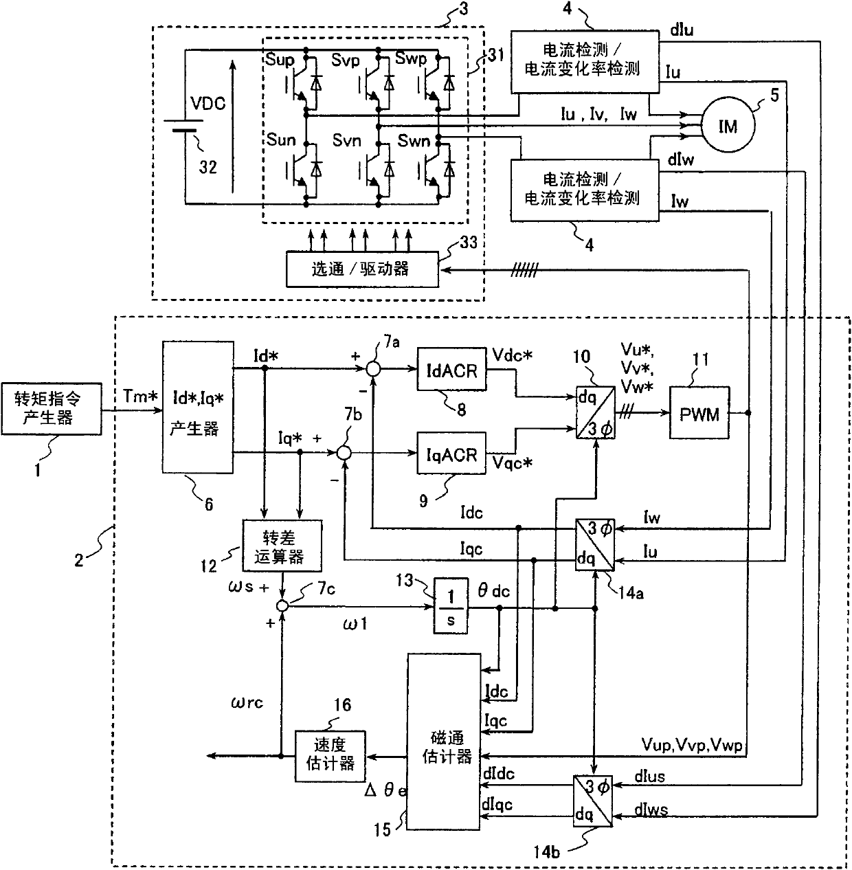
[0114] figure 1 It is a block diagram showing the configuration of the AC motor drive device according to the first embodiment of the present invention.

[0115] The purpose of this device is to drive a three-phase induction motor. The device generally includes a torque command generator 1; a controller 2; an inverter 3 comprising an inverter main circuit 31, an inverter power supply 32, and a gate / driver (gate / driver) 33; the current and the rate of change of the current A detector 4; and a three-phase induction motor 5 (hereinafter abbreviated as an induction motor) to be driven are constituted.

[0116] The torque command generator 1 is a means for giving the generation torque command Tm* to the induction motor 5 , and is a higher-level controller than the controller 2 . A speed controller for adjusting the rotation speed of the induction motor 5 may be provided at a higher level of the torque command generating device, but this is omitted in this embodiment.

[0117] Th...

Embodiment 2

[0135] Next, Embodiment 2 of the present invention will be described.

[0136] In the first embodiment, the controller 2 has been described with an analog circuit, but in order to realize digital control, high-speed processing is required. Of course, it is not impossible to realize digitalization if a dedicated gate logic is used, but in this case, the circuit scale will become huge.

[0137] In Example 2, on the premise of computers used in industrial applications, etc., the Figure 6 ~ Figure 10 A practical example is shown.

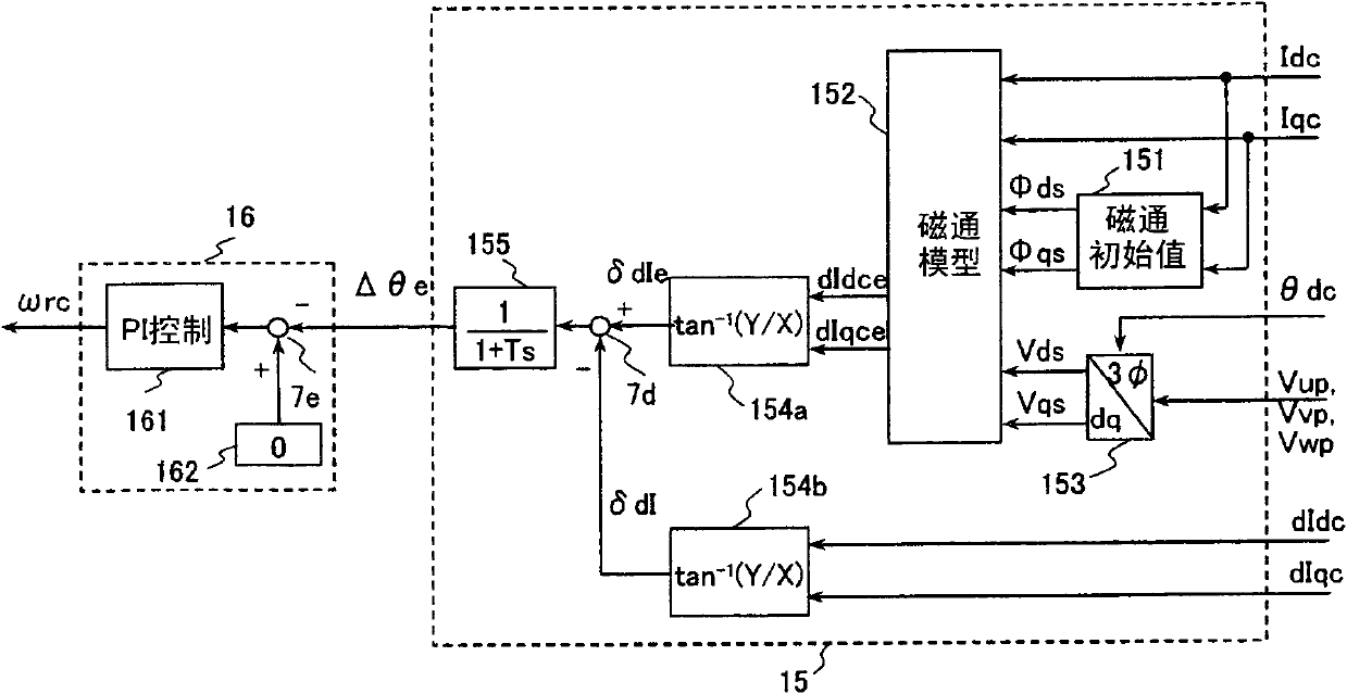
[0138] Image 6 It is a block diagram showing a controller 2B which is a characteristic part of the second embodiment. Replace this controller 2B figure 1 Introduced by the controller 2 in the system, Embodiment 2 is constituted.

[0139] exist Image 6 , for modules with part numbers 6 to 14 and 16, are the same as figure 1 Like numbered blocks shown are like blocks. The characteristic parts of this embodiment are the magnetic flux calculator ...

Embodiment 3

[0150] Next, Embodiment 3 of the present invention will be described.

[0151] In Embodiments 1 and 2, the control object is an induction motor, and in Embodiment 3, a permanent magnet synchronous motor (hereinafter abbreviated as a PM motor) is used. Compared with induction motors, PM motors can achieve smaller size and higher efficiency, so in the future, the applications that can be applied are expected to expand further.

[0152] Figure 11 It is a configuration diagram of the third embodiment. With embodiment 2 ( Image 6 ) is recorded on the basis. Controller 2C and Image 6 The controller 2B is roughly the same, except that the slip calculator 12 is deleted, there is no change. In addition, the motor is a PM motor 5C.

[0153] In the PM motor, since the drive frequency ω1 and the frequency ωrc of the rotational speed are necessarily synchronized, there is no need to add the slip frequency, and the control structure becomes more simplified. That is, the driving sy...


PUM


Abstract

Provided is a drive device for an alternating current motor which performs vector control on sensorless driving of the alternating current motor in an extremely low speed region without applying a harmonic voltage intentionally while maintaining an ideal PWM waveform. A current and a current change rate of the alternating current motor are detected, and a magnetic flux position inside of the alternating current motor is estimated and calculated in consideration of an output voltage of an inverter which causes this current change. The current change rate is generated on the basis of a pulse waveform of the inverter, and hence the magnetic flux position inside of the alternating current motor can be estimated and calculated without applying a harmonic wave intentionally.

Description

technical field [0001] The present invention relates to motor control technology for freely controlling the rotational speed and torque of AC motors such as induction motors and permanent magnet synchronous motors in an extremely low speed range near zero speed, and particularly relates to the rotational position angle of the motor's rotor that is not directly detected by a sensor Sensorless control of AC motor drives and motor vehicles with speed information. Background technique [0002] In the case of high-response, high-precision control of an AC motor, it is necessary to manage the torque of the motor. Among them, it is necessary to detect the rotational speed of the motor (in the case of a synchronous motor, the position (angle) information of the rotor) by the sensor, and then detect the phase current of the motor. The ground is separated into the torque current component and the excitation component current for control. This technique is widely used as vector contr...

Claims


Application Information

Patent Timeline
Patent Type & Authority Applications(China)
IPC IPC(8): H02P21/04H02P21/14H02P27/06H02P6/06H02P6/08H02P6/18H02P6/182H02P6/185H02P6/28H02P21/00H02P21/05H02P21/13H02P21/18H02P21/24H02P23/00H02P23/03H02P23/04H02P23/07H02P23/14H02P27/08
CPCY02T10/643H02P21/005Y02T10/725B60L15/025B60L15/08B60L2210/20Y02T10/642H02P21/04B60L2200/26H02P6/182H02P21/141H02P21/18Y02T10/64Y02T10/72
Inventor 岩路善尚金子大吾山本弘毅
Owner HITACHI LTD
Why Eureka
Try Eureka