Internal transient film heat-flow sensor of fuel cell

A heat flow sensor and fuel cell technology, used in fuel cells, fuel cell additives, material thermal development, etc., can solve the problem that the fuel cell heat flow density cannot be accurately reflected, the sensor positions cannot be accurately unified, and the fuel cell overall performance degradation and other problems, to achieve the effect of convenient and rapid disassembly and assembly of batteries, accurate measurement, and avoidance of fuel leakage

Active Publication Date: 2011-09-07
BEIJING UNIV OF TECH
View PDF2 Cites 28 Cited by
  • Summary
  • Abstract
  • Description
  • Claims
  • Application Information

AI Technical Summary

Problems solved by technology

[0002] The heat flow distribution inside the fuel cell is uneven and transient. Due to the special structure of the fuel cell itself, it is difficult to measure the heat flow distribution inside the fuel cell. So far, there is no simple and effective method that can accurately and conveniently solve the fuel cell. Measurement problem of heat flux distribution inside battery
[0003] Due to the large size and long response time of the traditional heat flow sensor, it cannot accurately reflect the real heat flow distribution inside the fuel cell
In addition, most of the measurement methods for various parameters inside the fuel cell are to implant the sensor into the flow channel of the fuel cell. The lead wire of the sensor is mainly a macro lead wire, which increases the internal resistance of the fuel cell and reduces the overall performance of the fuel cell. Improper installation can also lead to problems such as fuel cell leakage
In addition, the position of the sensor installed each time cannot be accurate and unified, which makes the comparison of the experimental results obtained before and after disassembling the battery poor. Therefore, a simple and effective measurement method is urgently needed to obtain the heat flux distribution inside the fuel cell.

Method used


Image

  • Internal transient film heat-flow sensor of fuel cell
  • Internal transient film heat-flow sensor of fuel cell
  • Internal transient film heat-flow sensor of fuel cell

Examples


Embodiment Construction

[0031] The accompanying drawings are specific embodiments of the present invention;

[0032] Below in conjunction with accompanying drawing, the content of the present invention is described in further detail:

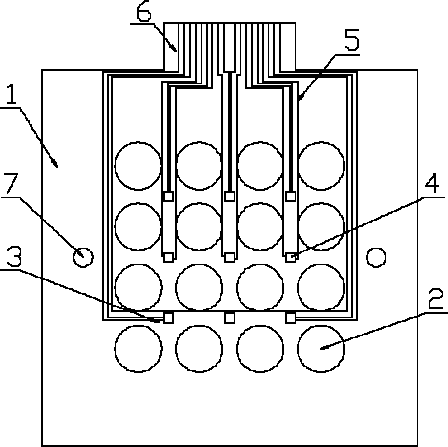
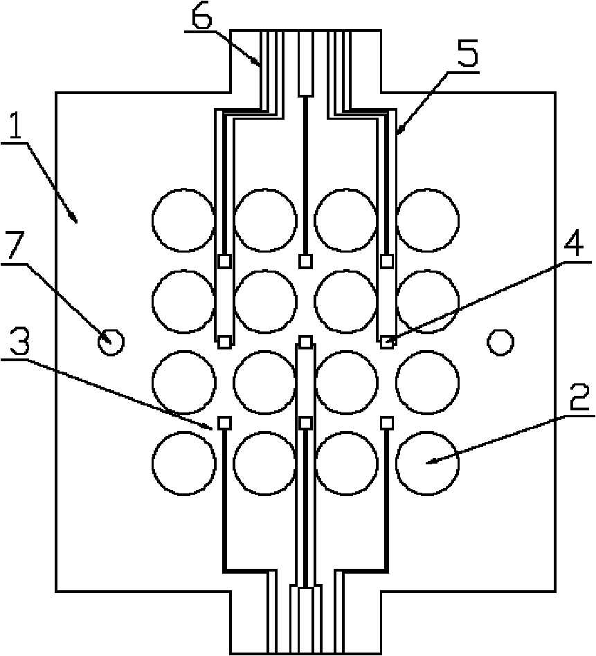
[0033] refer to figure 1 , 2 As shown, the position and number of standard wiring ports of the thin film heat flow sensor on the graphite flow field plate can be set as required. like figure 1 , figure 2 , image 3As shown, the present invention includes a thin film heat flow sensor 4 plated on the ribs 3 between the adjacent flow channels 2 on the graphite flow field plate 1 of the fuel cell, and the lead 5 of the thin film heat flow sensor 4 extends to the edge of the graphite flow field plate 1, The end of the lead wire 5 is provided with a standard wiring port 6 connected to the external circuit, and 7 in the figure is a positioning hole. In the heat flow density measuring device of the present invention, the thin film heat flow sensor 4 and its lead wires 5...


PUM

PropertyMeasurementUnit
thicknessaaaaaaaaaa
thicknessaaaaaaaaaa
thicknessaaaaaaaaaa

Abstract

The invention discloses a method for measuring internal heat-flow density distribution of fuel cells. In the method, a certain number of film heat-flow meters are arranged by employing a vacuum film coating technology on ribs between adjacent flow paths of a fuel cell graphite flow field board so as to measure the internal heat-flow density distribution of fuel cells. A single film heat-flow meter is formed by evaporating seven films on the rib of the graphite flow field board; the clad layers of the film heat-flow meter are determined according to the shape of a mask; a silica insulating layer is coated on the first layer; metal film thermocouples are coated on the second and third layers; a silica heat resistance layer is coated on the fourth layer; the metal film thermocouples are coated on the fifth and sixth layers; and a protective layer of a measuring head of the heat-flow meter is coated on the seventh layer. The wire of the film heat-flow meter is extended to the edge of the flow field board by the printing circuit technology on the rib of the graphite flow field board, and provided with a standard wiring access connected with an external circuit. The measuring method is simple, the processing and manufacturing are easy, the measurement is accurate, and the use is convenient.

Description

technical field [0001] The invention belongs to a transient thin film heat flow sensor inside a fuel cell, relates to the measurement of the instantaneous heat flow density distribution inside the fuel cell, and particularly relates to a method for measuring the transient heat flow density distribution. Background technique [0002] The heat flow distribution inside the fuel cell is not uniform and transient. Due to the special structure of the fuel cell itself, it is difficult to measure the heat flow density distribution inside the fuel cell. So far, there is no simple and effective method that can accurately and conveniently solve the fuel cell. The problem of measuring the heat flux density distribution inside the battery. [0003] Due to the large volume and long response time of the traditional heat flow sensor, it cannot accurately reflect the real heat flow density distribution inside the fuel cell. In addition, most of the measurement methods of various parameters ...

Claims


Application Information

Patent Timeline
Patent Type & Authority Applications(China)
IPC IPC(8): G01K7/02G01N25/20H01M8/04H01M8/0432
CPCY02E60/50Y02P70/50
Inventor 郭航聂志华叶芳马重芳
Owner BEIJING UNIV OF TECH
Why Eureka
Try Eureka