Measuring device of continuous spectrum bidirectional reflectance distribution function

A technology of bidirectional reflection distribution and measuring device, applied in the field of spectroscopy, can solve problems such as measuring continuous spectrum BRDF, etc., and achieve the effects of economical and feasible measuring device, simple device and high measuring accuracy

Inactive Publication Date: 2011-09-07
HARBIN INST OF TECH
View PDF1 Cites 23 Cited by
  • Summary
  • Abstract
  • Description
  • Claims
  • Application Information

AI Technical Summary

Problems solved by technology

[0007] In order to solve the problem that the existing spectral BRDF measuring device cannot measure continuous spectral BRDF in the visible light band, the present invention proposes a continuous spectral bidirectional reflectance distribution function measuring device

Method used


Image

  • Measuring device of continuous spectrum bidirectional reflectance distribution function
  • Measuring device of continuous spectrum bidirectional reflectance distribution function
  • Measuring device of continuous spectrum bidirectional reflectance distribution function

Examples


specific Embodiment approach 1

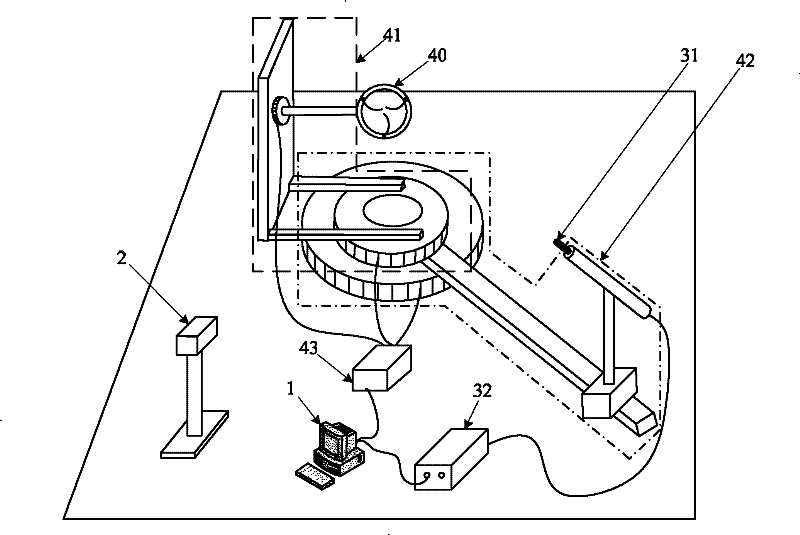
[0017] Specific implementation mode one: combine figure 2 Describe the present embodiment, the continuous spectrum bidirectional reflectance distribution function measuring device in the present embodiment, it comprises light source assembly 2, detector assembly, measuring frame assembly and control and data processing PC machine 1; Detector assembly comprises optical fiber probe 31 and spectrometer 32. The measuring frame assembly includes a sample ring 40, a sample horizontal and vertical rotation bracket 41, a detector position adjustment bracket 42 and a rotation controller 43; the sample ring 40 is installed on the sample horizontal and vertical rotation bracket 41, the The center point of the sample ring 40 is the center of rotation, and the horizontal and vertical rotation brackets 41 of the sample are used to drive the sample ring 40 to rotate on the horizontal plane and the vertical plane perpendicular to the horizontal plane with the center of rotation as the center ...

specific Embodiment approach 2

[0018] Specific implementation mode two: combination figure 2 and Figure 4 Describe this embodiment. The first difference between this embodiment and the specific embodiment is that the detector position adjustment bracket 42 includes a detector horizontal direction electric control rotation table 421, a guide rail 422, a slider 423, a detector pillar 424 and a detector adjustment frame 425 ; The detector horizontal direction electric control rotary table 421 is placed horizontally on the plane, and the detector horizontal direction electric control rotary table 421 is used to drive the detector to rotate on the horizontal plane; one end of the guide rail 422 is connected to the detector horizontal direction electric control rotary table 421 on the horizontal direction of the detector, and is linked with the electronically controlled rotary table 421 in the horizontal direction of the detector. A slider 423 is installed on the guide rail 422. The slider 423 is used to adjust...

specific Embodiment approach 3

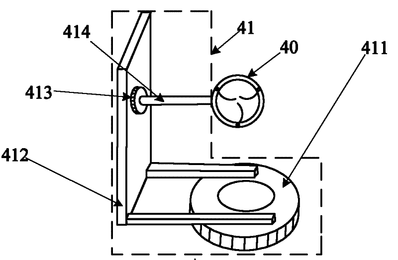
[0019] Specific implementation mode three: combination figure 2 and image 3 Describe this embodiment, the difference between this embodiment and specific embodiment 2 is that the sample horizontal and vertical direction rotation support 41 includes the sample horizontal direction electric control rotation table 411, the L-shaped connecting plate 412, the sample vertical direction electric control rotation table 413 and the sample holder 414; the sample horizontal direction electric control rotary table 411 is horizontally arranged on the upper part of the detector horizontal direction electric control rotary table 421, and the rotation axis of the sample horizontal direction electric control rotary table 411 coincides with the detector horizontal direction electric control rotary table 421 The electronically controlled rotary table 411 in the horizontal direction of the sample and the electronically controlled rotary table 421 in the horizontal direction of the detector rota...


PUM


Abstract

The invention relates to a measuring device of a continuous spectrum bidirectional reflectance distribution function, belonging to the fields of spectroscopy, computer graphics and machine vision and solving the problem that the traditional device can not measure the continuous spectrum BRDF (Bidirectional Reflectance Distribution Function) within a visible light wave band. A center point of a sample ring is a rotation center, and the sample ring is arranged on a sample horizontal and vertical direction rotating bracket; the sample horizontal and vertical direction rotating bracket is used for driving the sample ring to rotate on a horizontal surface and a vertical surface perpendicular to the horizontal surface by taking the rotation center as the center point; an optical fiber probe is arranged on a detector position regulation bracket, and a light path points at the rotation center; the detector position regulation bracket is used for driving the optical fiber probe to rotate on the horizontal surface by taking the rotation center as the center point and driving the optical fiber probe to make a one-dimensional linear motion with a motion trail penetrating through the rotation center; the signal output end of the optical fiber probe is connected with the input end of a spectrograph; a rotation controller is used for controlling the rotation of the sample horizontal and vertical direction rotating bracket and the detector position regulation bracket; a PC (Personal Computer) is connected with the spectrograph and the rotation controller; and light beams of a light source assembly are irradiated on the sample ring. The measuring device is used for measuring the continuous spectrum BRDF within the visible light wave band.

Description

technical field [0001] The invention belongs to the fields of spectroscopy, computer graphics and machine vision, and in particular relates to a device for measuring the light reflection characteristics of the surface of a material. Background technique [0002] Bidirectional Reflected Distribution Function (BRDF for short) is used to describe the light reflection characteristics of the hemispherical space on the material surface, mainly including spectral reflection characteristics and angle characteristics. This function contains five parameters: the wavelength λ of the incident light, the incident zenith angle θ i , incident azimuth reflection zenith angle θ r and reflection azimuth This function is defined as the ratio of the radiance in a reflection direction to the irradiance incident on the surface of the material (such as figure 1 ), whose expression is: [0003] formula one [0004] In the formula Spectral reflection radiance in the reflection direction,...

Claims


Application Information

Patent Timeline
Patent Type & Authority Applications(China)
IPC IPC(8): G01N21/55G01N21/25F16M11/06F16M11/18
Inventor 王付刚王治乐张伟汪洪源
Owner HARBIN INST OF TECH
Why Eureka
Try Eureka