Combined-type residual heat recovery system suitable for internal combustion engine

A technology of waste heat recovery system and internal combustion engine, which is applied in the direction of internal combustion piston engine, combustion engine, mechanical equipment, etc., can solve the problems of complex system, large volume, low efficiency, etc., and achieve the effect of reducing complexity, ensuring efficiency and improving efficiency

Inactive Publication Date: 2011-09-14
BEIJING INSTITUTE OF TECHNOLOGYGY
View PDF3 Cites 43 Cited by
  • Summary
  • Abstract
  • Description
  • Claims
  • Application Information

AI Technical Summary

Problems solved by technology

The advantages and disadvantages of the two are different. Among them, under the same high-temperature heat source and low-temperature cold source conditions: the waste heat recovery system based solely on the Rankine cycle has high

Method used


Image

  • Combined-type residual heat recovery system suitable for internal combustion engine
  • Combined-type residual heat recovery system suitable for internal combustion engine
  • Combined-type residual heat recovery system suitable for internal combustion engine

Examples


Embodiment Construction

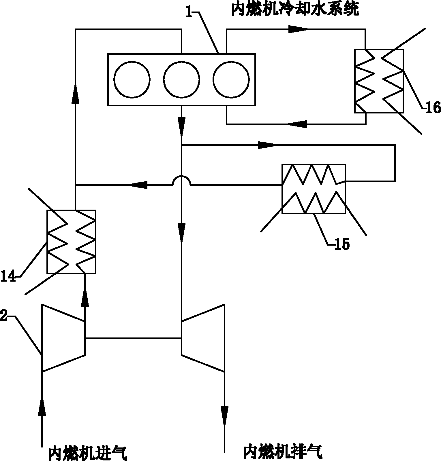
[0021] First, for figure 1 According to the analysis of the waste heat type of the internal combustion engine system shown, it can be known that the waste heat of the internal combustion engine is mainly distributed in the following parts:

[0022] ① Exhaust heat in the EGR cooler of the internal combustion engine;

[0023] ②Exhaust heat of the exhaust gas at the outlet of the turbine end of the internal combustion engine turbocharger;

[0024] ③ internal combustion engine cooling water heat;

[0025] ④The heat of the supercharged air at the outlet of the compressor end of the turbocharger of the internal combustion engine;

[0026] Among the waste heat mentioned above, ① and ② are medium-temperature waste heat, and ③ and ④ are low-temperature waste heat. If these different levels of energy can be recovered, the efficiency of the waste heat recovery system can be increased.

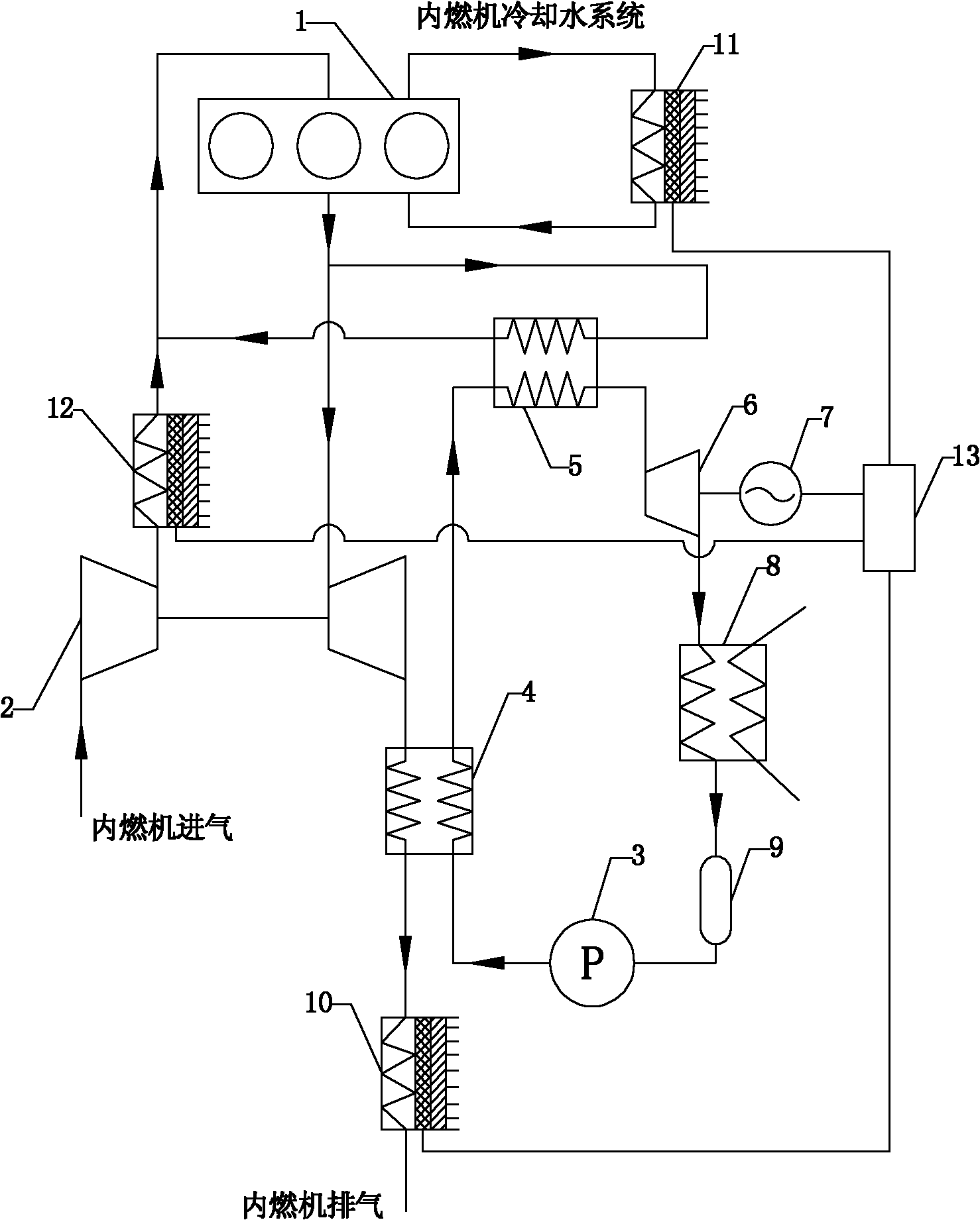
[0027] For this reason, the present invention aims at the characteristics of waste heat of interna...


PUM


Abstract

The invention discloses a rankine cycle and temperature difference power generating module combined-type residual heat recovery system suitable for an internal combustion engine. The system comprises an intermediate temperature residual heat recovery subsystem and a low temperature residual heat recovery subsystem; a hydraulic pump, an evaporator, an over-heating device, an expander, a condenser and a liquid storage device in the intermediate temperature residual heat recovery subsystem are sequentially connected, and the intermediate temperature residual heat in the internal combustion engine is recycled by adopting a rankine cycle technology by the intermediate temperature residual heat recovery subsystem; tail gas emitted by a turbine end of a turbosupercharger is taken as a heat source for the evaporator; tail gas of an EGR (exhaust gas recirculation) system of the internal combustion engine is taken as a heat source for the over-heating device; the expander is connected with a power generator through a crankshaft of the expander, and the power energy output end of the power generator is connected with an energy recovery device; and in the low temperature residual heat recovery subsystem, three semi-conductor temperature difference power generating modules are adopted to recycle the tail gas heat at the outlet end of the evaporator of the intermediate temperature residual heat recovery subsystem, the heat of the supercharge air at the end port of a gas compressor of the turbosupercharger and the heat of the cooling water of a motor. According to the invention, the rankine cycle and the temperature difference power generating module are adopted to be combined to recycle the residual heat of the internal combustion engine, so that not only is the fuel oil economy of the internal combustion engine improved, but also the volume of the integral residual heat recovery system is reduced.

Description

technical field [0001] The invention relates to a compound waste heat recovery system of Rankine cycle and thermoelectric power generation module suitable for internal combustion engines, which belongs to the field of heat exchange of internal combustion engines. Background technique [0002] With the rapid rise of energy prices, energy saving has become a common concern of all walks of life. About more than 60% of the heat in the internal combustion engine is released into the atmosphere through the exhaust gas and cooling system, and is not used. Therefore, it can be achieved by effectively using the waste heat of the internal combustion engine Improve fuel economy of internal combustion engines. [0003] figure 1 It is a schematic diagram of an existing internal combustion engine system with an EGR system. like figure 1 As shown, the air in the atmospheric environment is compressed into a high-pressure medium-temperature gas through the compressor end of the turbocharg...

Claims


Application Information

Patent Timeline
IPC IPC(8): F02G5/00F01D15/10H02N11/00
CPCY02T10/166Y02E20/14Y02T10/12
Inventor 魏名山张传明史磊马朝臣
Owner BEIJING INSTITUTE OF TECHNOLOGYGY
Why Eureka
Try Eureka