Light receiving and transmitting assembly for broadband parallel optics

An optical transceiver and optical technology, applied in the coupling of optical waveguides, etc., can solve the problems of complex implementation, large distribution range, reduced sensitivity, etc., to meet the requirements of parallel optical transceivers, reasonable distribution of gold wires, and improved process difficulty.

Inactive Publication Date: 2011-09-14
INNOLIGHT TECHNOLOGY (SUZHOU) LTD
View PDF4 Cites 34 Cited by
  • Summary
  • Abstract
  • Description
  • Claims
  • Application Information

AI Technical Summary

Problems solved by technology

[0004] However, the optical transceiver module implemented by this method has the following disadvantages: the electrical connection (such as gold wire connection) between the photoelectric array component and the corresponding substrate has a large distribution range and a long length, which is not suitable for the emission and detection of high-frequency signals. Undesirable noise interference will be introduced, which will make the signal worse and the performance of the device will be deteriorated; the use of optical fiber to directly couple with the optoelectronic device will reduce the sensitivity and poor coupling efficiency; at the same time, the process of assembly and alignment is difficult, the accuracy requirements are large and the implementation is complicated

Method used


Image

  • Light receiving and transmitting assembly for broadband parallel optics
  • Light receiving and transmitting assembly for broadband parallel optics
  • Light receiving and transmitting assembly for broadband parallel optics

Examples


Embodiment Construction

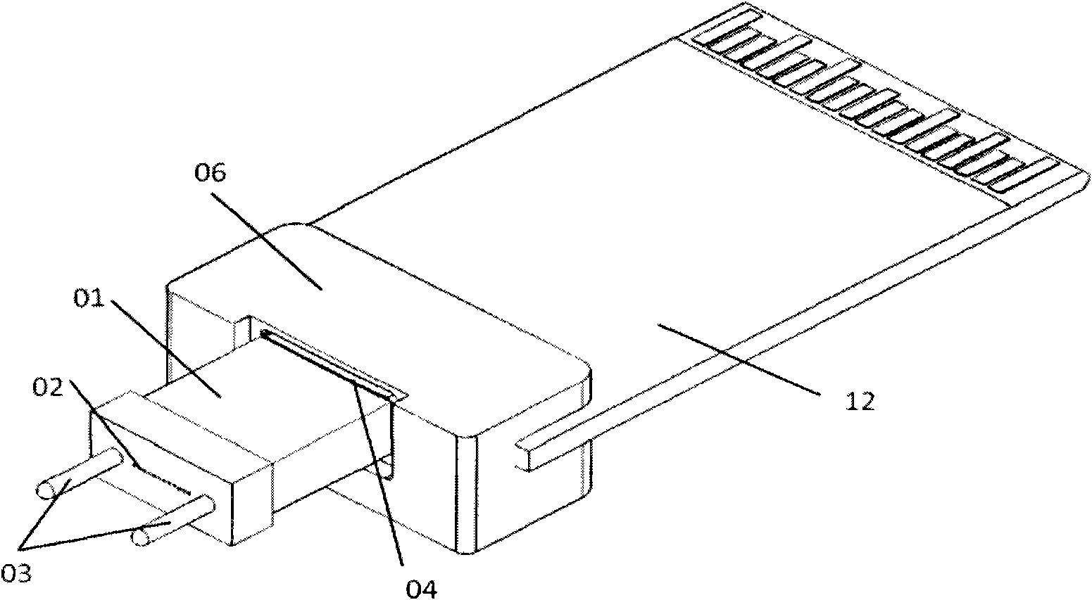
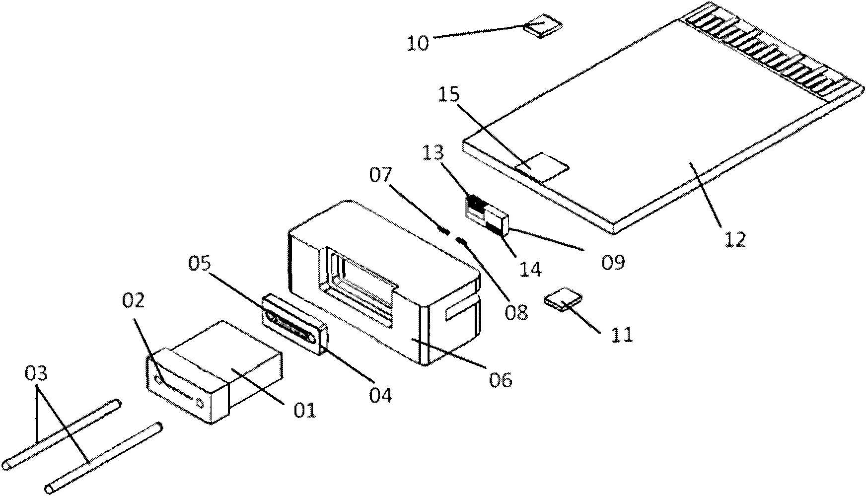
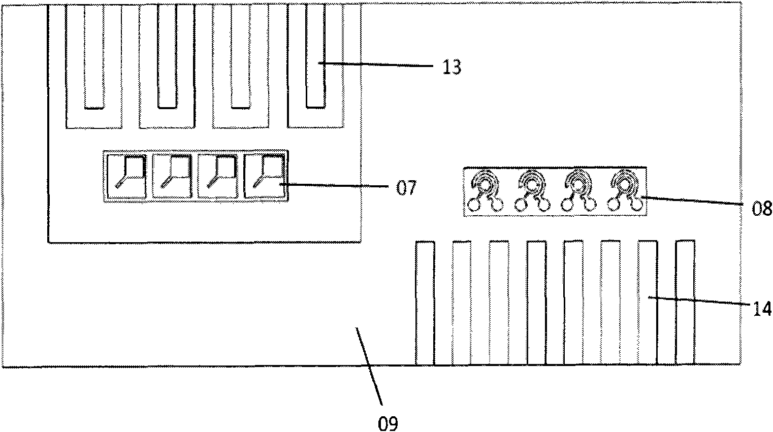
[0026] Such as figure 1 , figure 2 As shown, the optical transceiver assembly for broadband parallel optics includes an MT-type optical connector 01 and a lens holder 04, the lens holder 04 is connected to the MT-type optical connector 01, and the MT-type optical connector 01 is equipped with a straight line and uniform The arrayed optical fiber array 02, the lens holder 04 is embedded with a lens array 05 uniformly arranged in a straight line, the lens array 05 is aligned and coupled with the optical fiber array 02 in the MT optical connector; the lens holder 04 is provided with a positioning hole 16, MT The MT-type optical connector 01 is provided with a corresponding positioning hole, and the locating pin 03 is inserted into the positioning hole 16 on the lens holder 04 and the positioning hole on the MT-type optical connector 01 to make the lens holder 04 and the MT-type optical connector 01 The connection is fixed. Such as image 3 , the VCSEL laser array 07 and the P...


PUM


Abstract

The invention relates to a light receiving and transmitting assembly for broadband parallel optics, which comprises an MT (Manual Transmission) type optical connector and a lens base butted with the MT type optical connector, wherein the MT type optical connector is internally provided with linearly and uniformly arranged optical fiber arrays, the lens base is internally embedded with linearly and uniformly arranged lens arrays, the lens arrays and the optical fiber arrays in the MT type optical connector are aligned and coupled; and a VCSEL (Vertical Cavity Surfaceemitting Laser) array and a PD (Photoelectric Detector) array are assembled on a substrate and respectively connected with a conductive gold wire in a routing manner, the substrate is fixed and attached on the side surface of a PCBA (Printed Circuit Board Assembly) support member in a routing connection manner, a laser drive chip and a detector TIA (Totally Integrated Automation) chip are respectively arranged on an upper surface electrode and a lower surface electrode of the PCBA support member, and the PCBA support member connected with the substrate is abutted with the MT type optical connector connected with the lens base. The invention has the advantages of increasing the coupling efficiency of photoelectric devices and optical fibers, remarkably improving elements on the aspects of flexibility, process difficulty and the like, and meeting demands on parallel light receiving and transmitting.

Description

technical field [0001] The invention relates to an optical transceiver assembly for broadband parallel optics. Background technique [0002] With the rapid growth of human's demand for communication bandwidth, existing communication systems are facing two challenges of capacity and energy consumption. Due to the ability to provide greater bandwidth in a smaller space and lower energy consumption, the research and development of parallel optical modules is increasing. Parallel optical modules are multiple lasers aligned with multiple fibers in a single module - such as a 4-channel short-range transceiver module suitable for short-range high-bandwidth computing and switching applications, integrating four independent transmit and receive channels, and connected to A 12-channel multimode ribbon fiber. Due to the low power consumption brought by device integration and miniaturization, the parallel optical module generates and dissipates much less heat than multiple discrete de...

Claims


Application Information

Patent Timeline
Patent Type & Authority Applications(China)
IPC IPC(8): G02B6/43G02B6/42
Inventor 李伟龙孙雨舟常留勋施高鸿刘圣
Owner INNOLIGHT TECHNOLOGY (SUZHOU) LTD
Why Eureka
Try Eureka