Permanent magnet direct current (DC) speed-reducing motor

A geared motor, permanent magnet DC technology, applied in the direction of DC commutator, electric components, electrical components, etc., can solve the problems of large core loss, large change in contact voltage drop, long magnetic flux path, etc., to achieve a power-to-mass ratio and Effects of high torque volume factor, low vibration and noise, and short flux paths

Active Publication Date: 2013-02-06
久久艳阳福祉科技秦皇岛有限公司
View PDF6 Cites 0 Cited by
  • Summary
  • Abstract
  • Description
  • Claims
  • Application Information

AI Technical Summary

Problems solved by technology

[0002]The permanent magnet DC motors in the prior art, due to the long magnetic flux path, lead to a large core loss, and most of them have complex structures, large volumes, large noises, and poor performance Low, it is not suitable for applications with high requirements, and most of the brushes in the existing permanent magnet motors are not adjustable, which leads to large changes in contact voltage drop, which is very easy to cause safety accidents

Method used


Image

  • Permanent magnet direct current (DC) speed-reducing motor
  • Permanent magnet direct current (DC) speed-reducing motor
  • Permanent magnet direct current (DC) speed-reducing motor

Examples


Embodiment Construction

[0022] The technical scheme of the present invention is described in detail below in conjunction with the embodiment shown in the accompanying drawings:

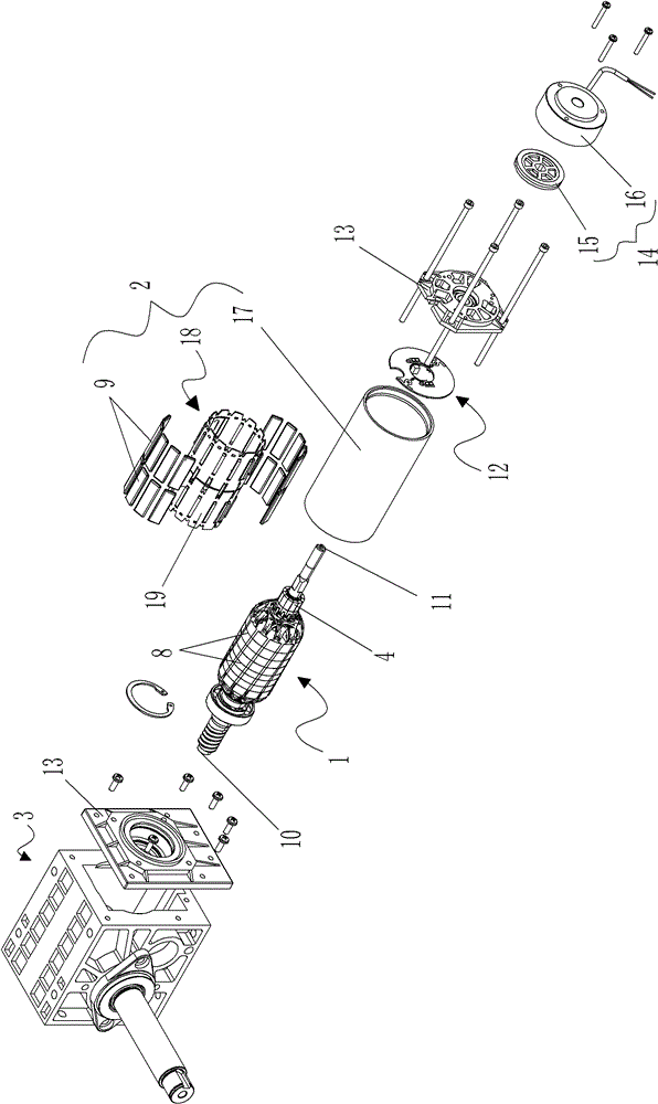
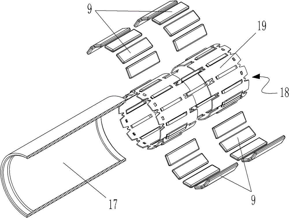
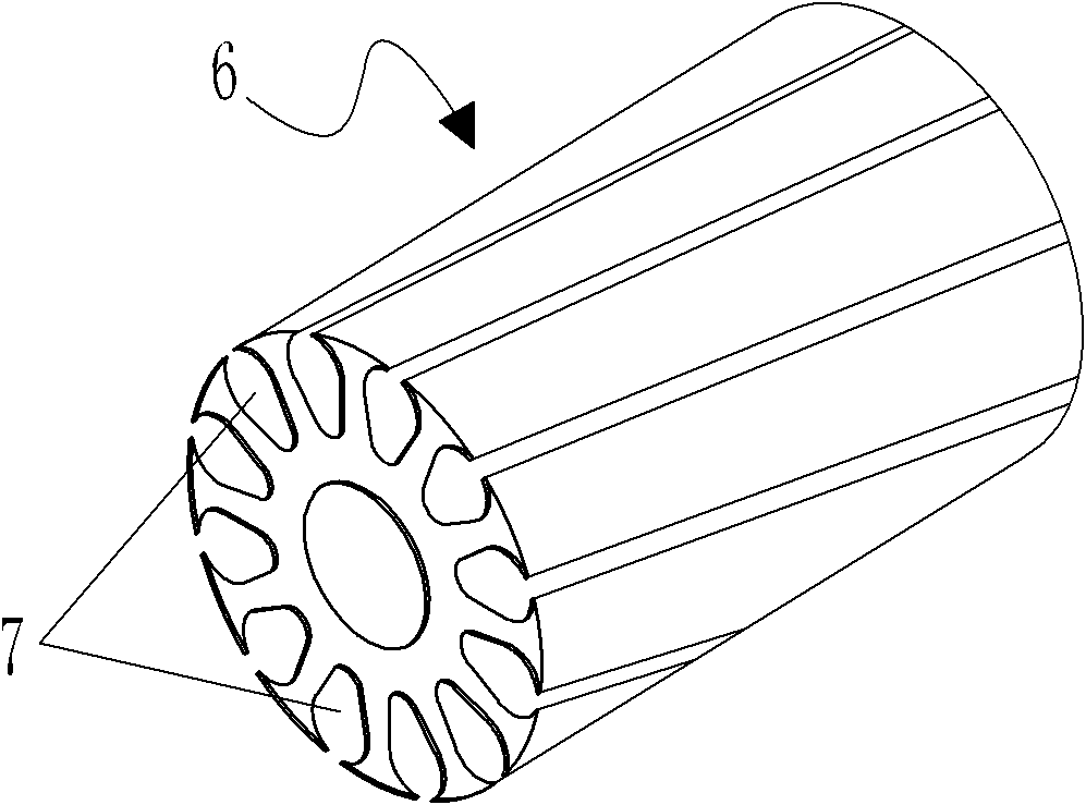
[0023] as attached figure 1 As shown, the permanent magnet DC geared motor of the present invention includes a rotor 1, a stator 2 arranged on the periphery of the rotor 1, a speed reducer 3 connected to the output end of the rotor 1, a commutator 4, and the rotor 1 includes a motor shaft 5 and is installed on The rotor core 6 on the motor main shaft 5, as attached image 3 and attached Figure 4 As shown, the outer peripheral wall of the rotor core 6 is provided with several grooves 7 distributed along its length direction, the outer circumference of the rotor core 6 is provided with windings 8, the stator 2 is provided with several permanent magnets 9, and the motor shaft 5 has a first end 10 and the second end 11, the commutator 4 is arranged on the second end 11, the commutator 4 is provided with a brush mechani...


PUM


Abstract

The invention discloses a permanent magnet direct current (DC) speed-reducing motor, which comprises a rotor, a stator arranged at the periphery of the rotor, a speed reducer connected to an output end of the rotor, and a commutator, wherein the rotor comprises a motor spindle and a rotor core which is arranged on the motor spindle; a plurality of grooves which are distributed along the length direction of the rotor core are formed on a peripheral wall of the rotor core; a winding is arranged at the periphery of the stator; a plurality of permanent magnets are arranged on the stator; the motor spindle is provided with a first end and a second end; the commutator is arranged at the second end; an electric brush mechanism is arranged on the commutator; and both ends of the stator are provided with an end cover which is fixed with the stator. Due to the integrated design of transmission, speed reduction, brake and manually fine tuning of the spindle of the permanent magnet DC speed-reducing motor, the motor can be better matched with equipment; due to the self-pressing design of the electric brush mechanism in the permanent magnet DC speed-reducing motor, commutation is guaranteed, and the motor operates without any fault for a long time; and the motor is compact in structure, small in volume, low in vibration and noise and suitable for popularization in industries.

Description

technical field [0001] The invention relates to a permanent magnet motor, in particular to a permanent magnet direct current geared motor. Background technique [0002] The permanent magnet DC motors in the prior art, due to the long magnetic flux path, lead to a large core loss, and most of them are complex in structure, large in size, high in noise, and low in performance, and are not suitable for applications in demanding occasions. Most of the brushes in permanent magnet motors are not adjustable, which leads to large changes in contact voltage drop, which can easily cause safety accidents. Contents of the invention [0003] The purpose of the present invention is to provide a small volume, high efficiency and energy saving permanent magnet direct current geared motor. [0004] In order to solve the problems of the technologies described above, the present invention adopts the following technical solutions: [0005] A permanent magnet DC deceleration motor, ...

Claims


Application Information

Patent Timeline
Patent Type & Authority Patents(China)
IPC IPC(8): H02K23/68H02K1/22H02K1/17H02K5/14
Inventor 陈利忠周占怀陈邦琼刘红月
Owner 久久艳阳福祉科技秦皇岛有限公司
Why Eureka
Try Eureka