White-light organic electroluminescent device and preparation method thereof

An electroluminescent device, white light technology, applied in the direction of electric solid device, semiconductor/solid state device manufacturing, electrical components, etc., can solve the problems of unfavorable carrier transport, high device turn-on voltage, difficulty in obtaining white light, etc. Efficiency, enhancing luminous intensity, suppressing annihilation effects

Inactive Publication Date: 2011-10-05
UNIV OF ELECTRONICS SCI & TECH OF CHINA
View PDF4 Cites 10 Cited by
  • Summary
  • Abstract
  • Description
  • Claims
  • Application Information

AI Technical Summary

Problems solved by technology

In the multi-emitting layer structure, due to the strong carrier capture ability of long-wavelength dyes compared with blue-light dyes, the recombination region is mainly concentrated in the light-emitting layer of long-wavelength dyes, and the energy transfer between the two can be quenched. Emission of blue light, so there is only very weak or even no blue light emission in the spectrum, and finally it is diff

Method used


Image

  • White-light organic electroluminescent device and preparation method thereof
  • White-light organic electroluminescent device and preparation method thereof
  • White-light organic electroluminescent device and preparation method thereof

Examples


Embodiment 1

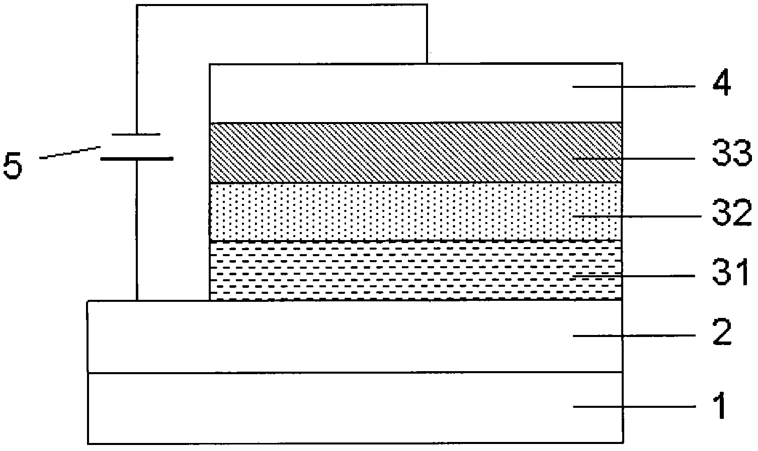
[0051] Such as figure 2 As shown, the blue phosphorescent light-emitting layer 31 of the device selects blue phosphorescent material Firpic doped mCP, and the complementary phosphorescent light-emitting layer 32 selects yellow phosphorescent dye (t-bt). 2 Ir(acac) is doped with BPhen, the material of the electron transport layer 33 is BPhen, and the cathode layer 4 is made of Mg:Ag alloy and Ag. The whole device structure is described as:

[0052] Glass / ITO / mCP:Firpic(20nm) / BPhen:(t-bt) 2 Ir(acac)(15nm) / BPhen(40nm) / Mg:Ag(200nm) / Ag(10nm)

[0053] The preparation method is as follows:

[0054] ①Using detergent, deionized water, acetone solution and ethanol solution to ultrasonically clean the glass substrate and the transparent conductive film ITO on it, and then dry it with high-purity nitrogen after cleaning. The ITO film on the glass substrate is used as the anode layer of the device. The sheet resistance of the ITO film is 10Ω / sq and the film thickness is 180nm.

[0055] ②Move the...

Embodiment 2

[0061] Such as figure 2 As shown, the blue phosphorescent light-emitting layer 31 of the device selects blue phosphorescent material Firpic doped mCP, and the complementary phosphorescent light-emitting layer 32 selects green phosphorescent dye (tpbi). 2 Ir(acac) is doped with BPhen, the material of the electron transport layer 33 is BPhen, and the cathode layer 4 is made of Mg:Ag alloy and Ag. The whole device structure is described as:

[0062] Glass / ITO / mCP:Firpic(20nm) / BPhen:(t-bt) 2 Ir(acac)(15nm) / BPhen(40nm) / Mg:Ag(200nm) / Ag(10nm)

[0063] The preparation process of the device is similar to Example 1.

Embodiment 3

[0065] Such as figure 2 As shown, the blue phosphorescent light-emitting layer 31 of the device selects blue phosphorescent material Firpic doped mCP, the complementary phosphorescent light-emitting layer 32 selects red phosphorescent dye PQIr doped BPhen, the electron transport layer 33 material is BPhen, and the cathode layer 4 uses Mg:Ag. Alloy and Ag. The whole device structure is described as:

[0066] Glass / ITO / mCP:Firpic(20nm) / BPhen:PQIr(15nm) / BPhen(40nm) / Mg:Ag(200nm) / Ag(10nm)

[0067] The preparation process of the device is similar to Example 1.


PUM

PropertyMeasurementUnit
Sheet resistanceaaaaaaaaaa
Film thicknessaaaaaaaaaa

Abstract

The invention discloses a white-light organic electroluminescent device, which comprises a substrate, an anode layer, a cathode layer and an organic functional layer arranged between the anode layer and the cathode layer, wherein the organic functional layer comprises a luminous layer; a blue phosphorescence dye is doped in the wide band gap main body matrix with hole transmission property, and a complementary phosphorescence dye is doped in the main body matrix with electron transmission and hole blocking properties, so that the hole and electrode resonance is transmitted onto the blue phosphorescence dye molecules to directly form excitonic composite luminescence; according to the hole blocking property of the complementary phosphorescence dye main body matrix, the complementary phosphorescence dye is prevented from trapping excessive hole current carriers, the luminous strength of the blue light dye is enhanced, and annihilation of excitons and polarons in the complementary phosphorescence luminous layer is inhibited at the same time, so that uniform and stable white light emission is obtained; and relatively weak blue light emission and even total quenching in the conventional white light device are solved, and the obtained phosphorescence white light device has simple structure, is easily controlled and efficient.

Description

Technical field [0001] The present invention relates to the technical field of organic electroluminescence devices, in particular to white light organic electroluminescence devices and a preparation method thereof. Background technique [0002] Compared with monochromatic devices, white light needs to cover the entire visible light region due to the width of its emission spectrum, so the device structure is more complicated. Therefore, the research of white organic electroluminescent devices (WOLED) started later than monochromatic light devices. But since WOLED was reported by J. Kido et al. (Appl. Phys.lett., 1994, 64, 815) in 1994, WOLED has aroused widespread interest. At present, as the most widely used white organic electroluminescent device with the most optimistic development prospects, it has begun to attract the attention of the industrial and scientific circles all over the world. As energy is the focus of competition among countries in the 21st century, energy conser...

Claims


Application Information

Patent Timeline
IPC IPC(8): H01L51/50H01L51/54H01L51/56
Inventor 于军胜雷霞蒋亚东赵萌
Owner UNIV OF ELECTRONICS SCI & TECH OF CHINA
Why Eureka
Try Eureka