
Non-relay optical fiber transmission system and method

A technology of optical fiber transmission and optical fiber transmission, which is applied in the field of optical fiber transmission, and can solve problems such as limited input sensitivity, low pump light power at 1480nm wavelength, and limited output power.

Active Publication Date: 2011-10-19
NO 34 RES INST OF CHINA ELECTRONICS TECH GRP
View PDF2 Cites 17 Cited by
  • Summary
  • Abstract
  • Description
  • Claims
  • Application Information

AI Technical Summary

Problems solved by technology

Therefore, in the current solutions for unrepeated optical fiber transmission systems, the useful 1480nm wavelength pump light power is very low, which limits the output power of the far-pumped EDFA optical power amplifier near the transmitting end; and the far-pumped EDFA optical power amplifier near the receiving end The input sensitivity of the preamplifier is limited, which leads to the limitation of the transmission distance between the remote-pumped EDFA optical power amplifier and the remote-pumped EDFA optical preamplifier, and the transmission distance of the entire unrepeated optical fiber transmission system is also limited.

Method used


Image

  • Non-relay optical fiber transmission system and method
  • Non-relay optical fiber transmission system and method
  • Non-relay optical fiber transmission system and method

Examples


Embodiment Construction

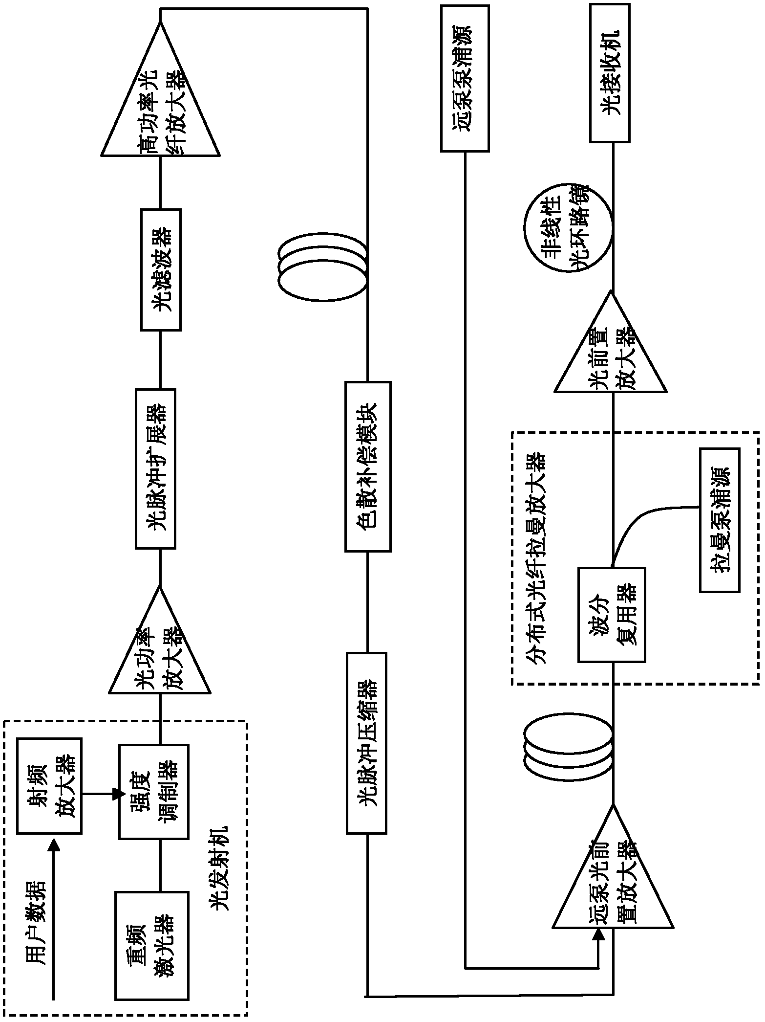
[0031] see figure 1 , a non-relay optical fiber transmission system of the present invention includes an optical transmitter, an optical power amplifier, an optical pulse expander, an optical filter, a high-power optical fiber amplifier, a dispersion compensation module, an optical pulse compressor, and a remote Pump optical preamplifier, distributed optical fiber Raman amplifier, optical preamplifier, nonlinear optical loop mirror and optical receiver. The remote-pumped optical preamplifier is connected with a remote pumping source, and the distributed optical fiber Raman amplifier is mainly composed of a Raman pumping source, a wavelength division multiplexer, and an optical signal transmission fiber behind the remote-pumped optical preamplifier. . The optical transmitter is mainly composed of a repetition frequency laser, an intensity modulator and a radio frequency amplifier. The input end of the radio frequency amplifier is connected with the user information, the outpu...


PUM


Abstract

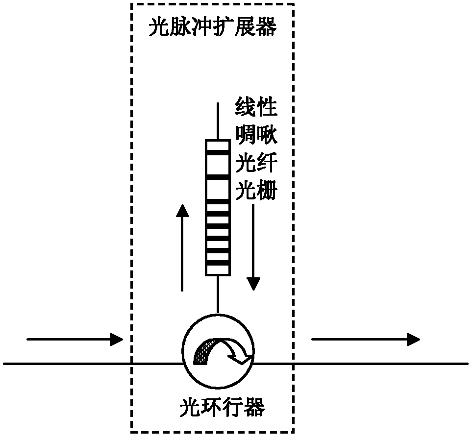
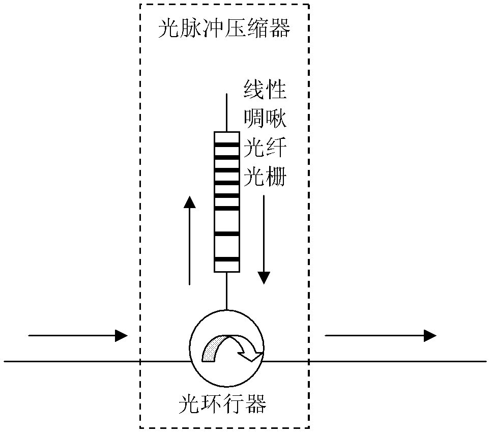
The invention discloses a non-relay optical fiber transmission system and method. The non-relay optical fiber transmission system comprises the following components that are sequentially connected with one another by transmission optical fibers: an optical transmitter, an optical power amplifier, an optical pulse expander, an optical fiber, a high-power optical fiber amplifier, a chromatic dispersion compensation module, an optical pulse compressor, a remotely-pumped optical preamplifier, a distributive optical fiber Raman amplifier, an optical preamplifier, a nonlinear optical loop mirror and an optical receiver. The remotely-pumped optical preamplifier is connected with a remotely-pumped source; and the distributive optical fiber Raman amplifier mainly consists of a Raman pumping source, a wavelength division multiplexer and an optical signal transmission fiber arranged behind the remotely-pumped optical preamplifier. In the invention, a linear chirped fiber grating is used for carrying out time-domain broadening on picosecond optical pulse; the picosecond optical pulse is amplified by the high-power amplifier and is transmitted in the optical fiber; the reversely arranged linear chirped fiber grating is used for compressing the time-domain expanded pulse and recovering the time-domain expanded pulse as the picoscond pulse, thus obtaining time spread gain, thereby leading the transmission distance of the non-relay optical fiber transmission system to be extended.

Description

technical field [0001] The invention relates to the field of optical fiber transmission, in particular to a non-relay optical fiber transmission system and method. Background technique [0002] At present, the solution of the non-relay optical fiber transmission system at home and abroad is to use the remote pump EDFA optical power amplifier at a distance of tens of kilometers (50-70km) on the side close to the transmitter, and to use a remote pump EDFA optical power amplifier at a distance of 100 kilometers (110- 140km) distance pump EDFA optical pre-amplifier is used, and distributed optical fiber Raman amplifier is used on the receiver side. Since the pump light with a wavelength of 1480nm at the transmitter needs to travel tens of kilometers (50-70km) to reach the remote pump EDFA optical power amplifier, and in the long-distance transmission process, the optical fiber will be affected by the stimulated Raman scattering effect , most of the energy of its pump light will...

Claims


Application Information

Patent Timeline
IPC IPC(8): H04B10/17H04B10/18
Inventor 吴国锋罗青松刘志强
Owner NO 34 RES INST OF CHINA ELECTRONICS TECH GRP
Learn More