

Method for reducing NO by using iron catalyst
An iron catalyst and carbon monoxide technology, applied in chemical instruments and methods, separation methods, dispersed particle separation, etc., can solve the problems of ammonia leakage and expensive use, and achieve sufficient supply, safe and reliable costs, and no secondary pollution Effect
- Summary
- Abstract
- Description
- Claims
- Application Information
AI Technical Summary
Problems solved by technology
Method used
Image

Examples
Embodiment 1
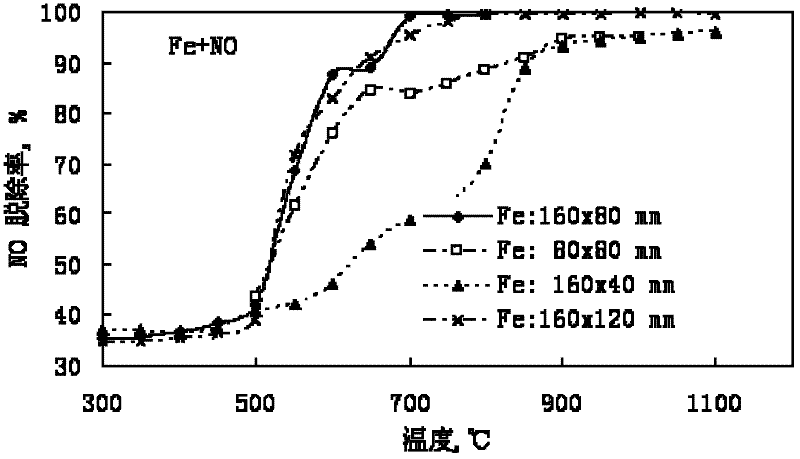
[0023] Under the following conditions: use high-purity nitrogen (N 2 ) is the trim gas, NO gas with a volume percentage of 10% (N 2 As the balance gas) is the NO gas source, they are evenly mixed and metered by the rotameter to form the simulated flue gas, the flow rate of the simulated flue gas is 1.5L / min, and the volume percentage of NO in the flue gas is 0.05%. The above-mentioned simulated flue gas is passed into a horizontally arranged ceramic tube with an inner diameter of 2.9cm. The ceramic tube is placed horizontally in an electric heating furnace for heating. The length of the heating section is 30cm. The heating temperature is controlled by a program, and the temperature range is 300-1100°C . Use barbed wire as a catalyst, and the specifications of the barbed wire are: the size of a single grid is 6×6mm, and the diameter of the wire is 0.5mm. The barbed wire mesh is a rectangular mesh with length×width=(80~160)×(40~120)mm, which is rolled into a roll along its sho...
Embodiment 2
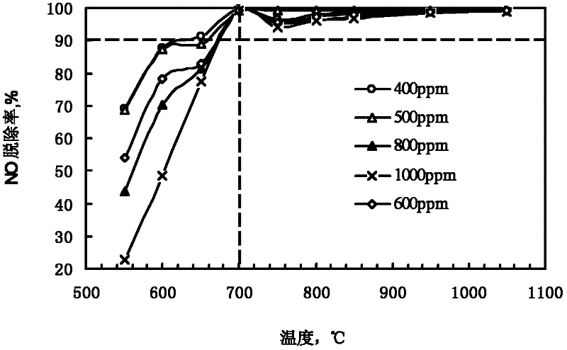
[0026] Under the following conditions: the flue gas flow rate is 1.5L / min, the volume percentage of NO in the flue gas is 0.04%-0.1%, and the temperature range is 300-1100°C. Use barbed wire as a catalyst, and the specifications of the barbed wire are: the size of a single grid is 6×6mm, and the diameter of the wire is 0.5mm. The barbed wire is a rectangular net with length × width = 160 × 80mm, rolled into a roll along its short side.
[0027] figure 2 for the experimental results. The results show that when the temperature exceeds 700°C, the flue gas contains different volume percentages of NO, and the removal rate can reach more than 90%.
Embodiment 3
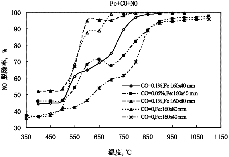
[0029] Under the following conditions: the flue gas flow rate is 1.5L / min, the volume percentage of NO in the flue gas is 0.05%, and the temperature range is 300-1100°C. Use barbed wire as a catalyst, and the specifications of the barbed wire are: the size of a single grid is 6×6mm, and the diameter of the wire is 0.5mm. The barbed wire is a rectangular net with length × width = 160 × 80mm, rolled into a roll along its short side. Add 0.05%-0.1% CO in the flue gas by volume.
[0030] image 3 for the experimental results. The experimental results show that with the increase of reaction temperature, the removal efficiency of NO under the action of iron and CO increases gradually. When the volume percentage of CO is 0.1%, NO is almost completely removed after the temperature exceeds 800 °C. When the volume percentage of CO is 0.05%, NO is almost completely removed when the temperature exceeds 950 °C.
[0031] The comparison found that the amount of barbed wire had a signifi...
PUM
 Abstract
Description
Claims
Application Information