Miniature projection liquid crystal on silicon (LCOS) optical engine

An optical engine and micro-projection technology, applied in optics, optical components, light sources, etc., can solve the problems of low optical utilization and power consumption, miniature projector structure reduction, violation of micro-projection, etc., and achieve low manufacturing cost and high optical quality. The effect of utilizing the utilization rate and improving the overall performance

Inactive Publication Date: 2011-11-16
FUJIAN INST OF RES ON THE STRUCTURE OF MATTER CHINESE ACAD OF SCI
View PDF6 Cites 2 Cited by
  • Summary
  • Abstract
  • Description
  • Claims
  • Application Information

AI Technical Summary

Problems solved by technology

The luminous efficiency of LED decreases continuously with the increase of brightness. Although the efficiency of LCOS is improved, there is still the problem of low projection brightness, and the use of new LEDs will cause problems of power consumption and heat dissipation, making the volume too large , For example, the size of micro-projectors above 30 lumens on the market is much larger than that of 10 lumens, and even doubles, which is contrary to the development direction of micro-projection technology.
[0005] The color filter type CF-LCOS projection technology only needs to use a single white light LED to greatly reduce the structure of the micro projector, and the optical path design and circuit design are simple, the image refresh rate is above 90HZ, and the heat dissipation structure is easy to design. At the same time, its optical utilization and power consumption are lower than other micro-projection technologies, which will affect the projection quality

Method used


Image

  • Miniature projection liquid crystal on silicon (LCOS) optical engine
  • Miniature projection liquid crystal on silicon (LCOS) optical engine
  • Miniature projection liquid crystal on silicon (LCOS) optical engine

Examples


Embodiment 1

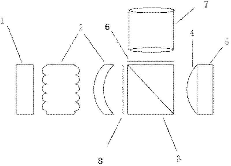
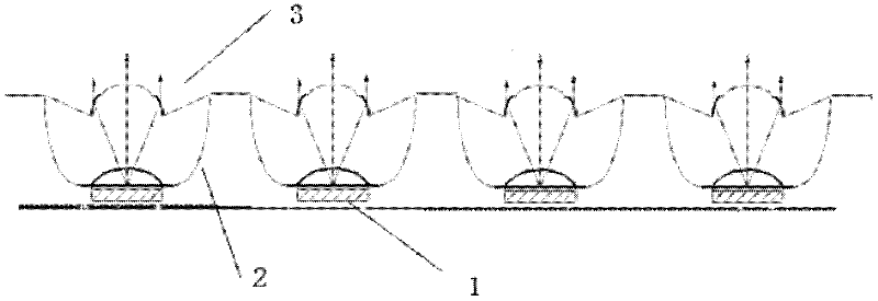
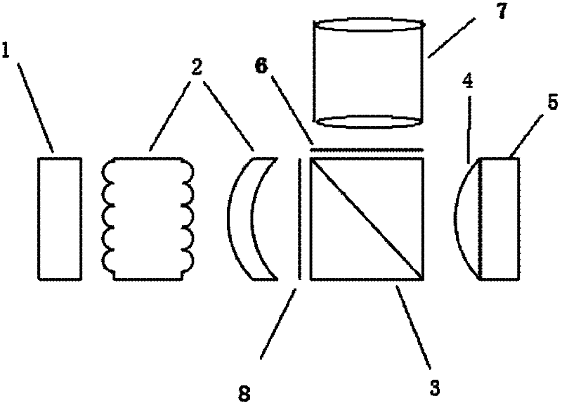
[0012] Embodiment one: if figure 1 The micro-projection LCOS optical engine system of the shown embodiment is provided with a surface light source module 1, an array lens combination 2, a PBS prism 3, a field lens 4, an LCOS chip 5, a polarizer 6, and a projection module 7 in sequence along the light propagation direction. , UV absorbing sheet 8. The surface light source module 1 uses a plurality of high luminous efficiency and low power white LEDs to form an array, such as figure 2 The structure diagram of the surface light source module shown in , and the structure diagram of the parabolic reflective bowl and the improved Fresnel lens shown in Figure 3. 2 in Figure 3 is a parabolic reflective bowl, which is coated with a cold reflective film inside, which can reflect visible light and pass through infrared and ultraviolet radiation, thereby reducing the amount of harmful radiation entering the optical system. The light with a large divergence angle is reflected by the ref...


PUM


Abstract

The invention provides a miniature projection liquid crystal on silicon (LCOS) optical engine, which aims to solve the problem of over-low projection brightness of the conventional miniature projector. The miniature projection LCOS optical engine comprises an area light source module, an array lens assembly, a polarizing beam splitter (PBS) prism, a field lens, an LCOS chip, a polaroid sheet and a projection objective, which are fixed on an engine base and sequentially arranged along the propagation direction of light rays; the area light source module is formed by combining a parabolic reflective bowl, a white light light-emitting diode (LED) array and a Fresnel lens; the array lens assembly consists of an array lens and a converging lens; the area light source module is arranged at the bottom of the parabolic reflective bowl by a white light LED; emitted light beams are combined by a fly's-eye lens; an approximately-parallel light beam enters the PBS lens; the LCOS chip is adhered to the outside of a plane convex lens; and a formed image enters the projection objective through the polaroid sheet. The miniature projection LCOS optical engine is novel in structure and better meets requirements of the existing customer on miniature structure and projection brightness.

Description

technical field [0001] The invention belongs to the technical field of micro-projection display, and in particular relates to an optical imaging system, in particular to a micro-projector LCOS optical engine. technical background [0002] As a window for man-machine contact and information transmission, display technology has been used in various aspects such as entertainment, industry, military, transportation, education, aerospace, satellite remote sensing, and medical care. The display industry has become a pillar industry of the sub-information industry. Projection display refers to a method or device in which light is controlled by planar image information, and the image is magnified and displayed on a projection screen by using an optical system and a projection space. With the development of economy and technology and the continuous expansion of the market, projectors are developing in the direction of high performance, integration, and portability. Among them, ...

Claims


Application Information

Patent Timeline
Patent Type & Authority Applications(China)
IPC IPC(8): G03B21/20G03B21/14G02B3/00G02B3/02G02B3/08G02B5/30F21V5/04F21Y101/02
Inventor 吴少凡王晓伟郑熠
Owner FUJIAN INST OF RES ON THE STRUCTURE OF MATTER CHINESE ACAD OF SCI
Why Eureka
Try Eureka