Biological Aerated Filter and Its Sewage Treatment Process

A biological aerated filter and sewage treatment technology, which is applied in the field of sewage treatment, can solve problems such as heavy maintenance workload, increased equipment cost investment, and complicated operation methods, and achieves prolonged residence time, extended backwash cycle, and low energy consumption Effect

Active Publication Date: 2011-11-30
江苏林格环境工程集团有限公司
View PDF13 Cites 10 Cited by
  • Summary
  • Abstract
  • Description
  • Claims
  • Application Information

AI Technical Summary

Problems solved by technology

This method not only increases the equipment cost investment, but also complica

Method used


Image

  • Biological Aerated Filter and Its Sewage Treatment Process
  • Biological Aerated Filter and Its Sewage Treatment Process
  • Biological Aerated Filter and Its Sewage Treatment Process

Examples


Embodiment 1

[0060] Industrial painting wastewater such as automobile painting usually has high CODcr content and extremely low ammonia nitrogen content. The main pollutants are heavy metals, complexes, phosphorus and other substances. After pretreatment, the COD is usually about 1500mg / l, and after acid treatment After that, the pH value was adjusted to 3.5; after micro-electrolytic oxidation catalysis, the pH value was adjusted to 10 by adding alkali, and the flocculation and precipitation were carried out; then the pH value was adjusted to 7.5 by adding acid, and the COD was 600~750 mg at this time / l, BOD 5 100~200mg / l. The sewage treated in the above steps is used as the influent of the present invention.

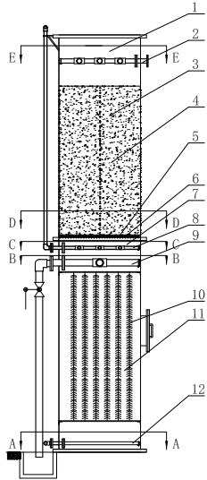
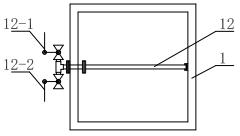
[0061] Feed water into the bottom water inlet pipe 12 of the biological aerated filter tank body 1 of the present invention, after the sewage passes through the filler layer in the anoxic zone and the filter material layer in the aerobic zone, pre-denitrification treatment is carr...

Embodiment 2

[0063] Domestic sewage usually has a high content of ammonia nitrogen, COD / BOD 5 >30%, relatively high, easy to biochemical treatment. COD is 300~400 mg / l after the pretreatment process in similar embodiment 1, BOD 5 150-200mg / l, ammonia nitrogen value ≥ 30mg / l, the domestic sewage after the above-mentioned steps is used as the influent of the present invention.

[0064] Feed water into the bottom water inlet pipe 12 of the biological aerated filter tank body 1 of the present invention, after the sewage passes through the filter material layer in the anoxic zone and the packing layer in the aerobic zone, pre-denitrification treatment occurs, and passes through the top The drain pipe 2 discharges the tank body 1; since the ammonia nitrogen content in the domestic sewage is very high, this embodiment needs to return the effluent. According to the level of ammonia nitrogen content and the specific denitrification requirements, the return flow can reach up to 300%; at the same ti...


PUM


Abstract

The invention discloses a biological aerated filter and a sewage treatment process thereof. An inner cavity of a tank body is divided into an anoxic reaction region at the lower half part and an aerobic reaction region at the upper half part. A backwashing drain pipe, an aerator pipe and a filter material bearing structure are arranged between the anoxic reaction region and the aerobic reaction from bottom to top sequentially. Biological filter materials in the aerobic reaction region are stacked on the filter material bearing structure. The anoxic reaction region is provided with a pluralityof groups of hangers for hanging the anaerobic biological filter materials. The lower part of the tank body is provided with a water inlet pipe. The top of the tank body is provided with a drain pipe. The drain pipe is provided with a bypass return pipe communicated with the water inlet pipe at the bottom of the tank body. In the invention, the anoxic region and the aerobic region which are arranged separately conventionally are integrated to carry out pre-denitrification, so that not only are pollutants in water effectively removed, but also the pollutant removing efficiency is high, equipment is simple and the biological aerated filter is easy to operate and is convenient to maintain.

Description

technical field [0001] The invention relates to the field of sewage treatment, in particular to a biological aerated filter and a treatment process for various types of sewage. Background technique [0002] Biological aerated filter is a new sewage treatment process that emerged in the early 1990s. It has been widely popular in developed countries such as Europe, America and Japan. This process has the functions of removing SS, COD, BOD, nitrification, nitrogen removal, phosphorus removal, and harmful substances. Function, which is characterized by the integration of biological oxidation and interception of suspended solids, saving the follow-up sedimentation tank (secondary sedimentation tank), its volume load and hydraulic load are large, the hydraulic retention time is short, the required infrastructure investment is small, the effluent water quality is good, and the operation Low energy consumption and low operating costs. [0003] Because the biological aerated filter ...

Claims


Application Information

Patent Timeline
IPC IPC(8): C02F3/30
Inventor 周伟周岳荣吴良基
Owner 江苏林格环境工程集团有限公司
Why Eureka
Try Eureka