

fiber optic geophone
A technology of geophones and optical fibers, applied in seismic signal receivers, clad optical fibers, optical waveguides, etc., can solve the problems of expensive demodulation equipment, susceptibility to electromagnetic interference, and high noise, and achieve easy multiplexing and networking , Low demodulation cost, simple device demodulation effect
- Summary
- Abstract
- Description
- Claims
- Application Information
AI Technical Summary
Problems solved by technology
Method used
Image

Examples
Embodiment 1
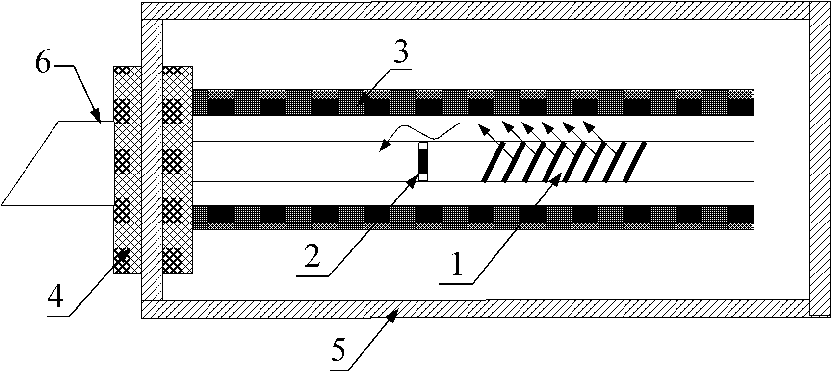
[0029] Such as figure 1 As shown, in this embodiment, a fiber optic geophone includes a tilted fiber grating 1, a cladding-core energy recoupling structure 2, a polymer elastic tube 3, a support member 4, a housing 5 and an optical fiber wire 6; One end of the elastic tube 3 is fixed on the supporting member 4, and the other end is suspended in the air to sense the vibration; the tilted fiber grating 1 and the cladding-core energy recoupling structure 2 are all encapsulated in the polymer elastic tube 3; the outer side of the polymer elastic tube 3 is composed of The shell 5 protects; the polymer elastic tube 3 is connected with an external light source and a photodetector through an optical fiber wire 6 . The polymer elastic tube 3 protects the internal tilted fiber grating 1 and at the same time utilizes its own high elasticity to effectively transmit environmental vibrations to the internal optical fiber.
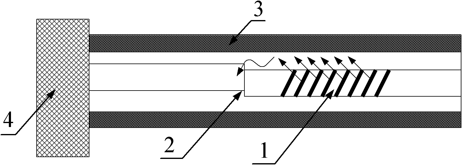
[0030] Such as figure 2 As shown, the cladding-core energy recou...
Embodiment 2
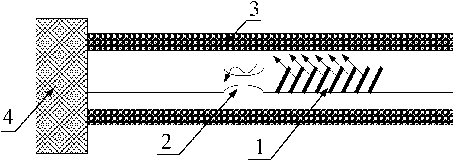
[0036] Present embodiment except following feature other structures are with embodiment 1: as image 3 As shown, the cladding-core energy recoupling structure 2 is processed by the optical fiber tapering method. Among them, when the diameter of the untapered cladding is 125um, the diameter of the fiber taper is controlled between 60 and 90um, which not only ensures sufficient cladding mode-core mode coupling channels, but also prevents the fiber taper from being too thin to reduce its mechanical strength. Similarly, the position of the tapered fiber should be as close as possible to the tilted fiber grating, with a typical spacing of 2 to 5 mm. In this embodiment, 3 mm is selected. The size of the whole sensing probe is less than 15mm.
[0037] The tilted fiber grating 1 adopts a tilted grating, and the tilt angle of the grating is 4 degrees.
PUM
 Abstract
Description
Claims
Application Information