Heat recovery incinerator using combustible waste as fuel

A technology of heat recovery and waste, applied in the direction of incinerators, combustion methods, combustion types, etc., can solve the problems of long time, energy and cost, accelerated corrosion of combustion gas, and shortened life, so as to reduce the burden of economic costs and improve reprocessing Efficiency, effect of preventing thermal deformation

Inactive Publication Date: 2011-12-21
李钟弼
View PDF6 Cites 8 Cited by
  • Summary
  • Abstract
  • Description
  • Claims
  • Application Information

AI Technical Summary

Problems solved by technology

[0007] However, in the incinerator of the above-mentioned structure, if figure 1 and figure 2 As shown, the turntable 111 and the nozzle 112 of the combustion plate 110 manufactured by welding or assembling with heat-resistant steel castings or stainless steel, and the second oxygen supply pipe 125 arranged in the center of the combustion chamber 100 along the vertical direction from the upper cover 103 The surface is directly exposed to the high temperature and combustion gas of the combustion chamber 100, so thermal deformation due to high temperature occurs in various parts made of metal, and the corrosion is accelerated by the combustion gas, resulting in a shortened life.
Therefore, the maintenance and replacement of the combustion plate 110 and the second oxygen supply pipe 125 bring about complicated operation and economical burden.
[0008] In addition, not only b

Method used


Image

  • Heat recovery incinerator using combustible waste as fuel
  • Heat recovery incinerator using combustible waste as fuel
  • Heat recovery incinerator using combustible waste as fuel

Examples


Embodiment Construction

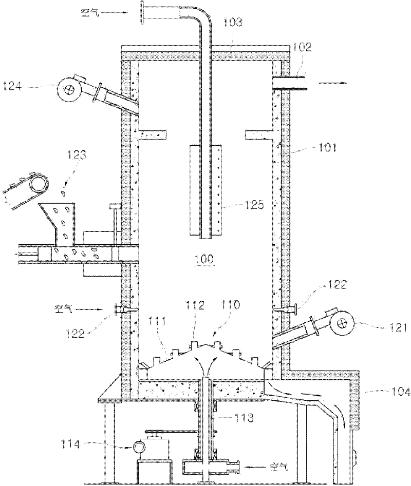
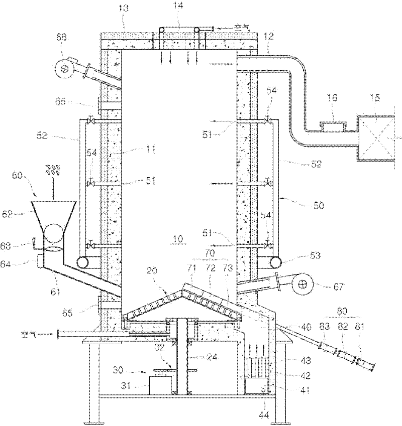
[0045] Hereinafter, preferred embodiments of the present invention will be described in detail with reference to the drawings. image 3 It is a cross-sectional structure diagram showing the heat recovery incinerator using combustible waste as fuel of the present invention. The incinerator of the present invention is provided with: a combustion chamber 10 surrounded by a wall 11 made of a refractory and heat-resistant material Combustion plate 20 is rotatably installed at the lower part of the combustion chamber 10, on which fuel is placed for combustion; and discharge port 12 is formed on the wall 11 at the upper part of the combustion chamber 10.

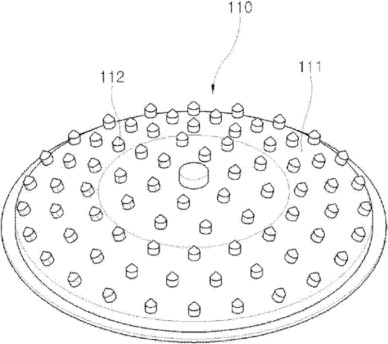
[0046] The above-mentioned combustion plate 20 is arranged with a certain gap with the inner wall of the lower part of the combustion chamber 10, such as Figure 4 As shown, a conical turntable 22 is made of alloy steel such as stainless steel, and a plurality of nozzles 21 for injecting combustion air in a certain direction are pr...


PUM


Abstract

Disclosed is a heat recovery incinerator using combustible waste as fuel. The heat recovery incinerator can protect the combustion plate and the second oxygen supply pipe installed in the combustion chamber so that they will not be damaged by the high temperature of the combustion chamber and the combustion exhaust gas. Thermal deformation and corrosion occur, thereby prolonging the life, and preventing the problem of reducing the performance of the internal structure due to the adhesion of foreign matter on the inner wall surface of the combustion chamber; and, performing complete combustion on the combustion exhaust gas generated during fuel combustion to make the exhaust gas The harmful substances contained are minimized, so that air pollution can be prevented. The heat recovery incinerator using combustible waste as fuel according to the present invention comprises: a combustion chamber surrounded by a wall made of a refractory and heat-resistant material layer; a combustion plate rotatably arranged on the side of the combustion chamber The lower part is for placing fuel for combustion. The above-mentioned combustion plate includes: a conical turntable made of alloy steel, a plurality of nozzles protruding from the upper surface of the turntable, and the plurality of nozzles inject combustion air in a certain direction; a rotating shaft is connected to the central lower part of the turntable, The turntable is supported in a rotatable manner; the air manifold is arranged at the lower part of the turntable to supply combustion air to the interior of the turntable; the heat-resistant and fire-resistant cover member covers the upper surface of the turntable to the protruding height of the nozzle to avoid Avoid protruding the nozzles to the side of the combustion chamber while exposing the upper surface of the turntable.

Description

technical field [0001] The invention relates to a heat recovery incinerator using combustible waste as energy fuel. Background technique [0002] Among wastes generated in various industrial fields and daily life, industrial materials and daily necessities made of various synthetic resins such as flammable polyethylene, plastics, and tires are the mainstream. Some of them are landfilled or incinerated after passing through the separation process. However, in the current situation where the green revolution is planned to be carried out in terms of policies in response to global warming, environmental pollution, and water quality improvement, if waste resources are landfilled, there may be serious Very big economic loss, and can produce the dual problem of polluting soil and contaminating groundwater. In addition, when the waste is incinerated, the combustion exhaust gas generated during the incineration of the waste will produce lethal soot and harmful gases, thereby polluti...

Claims


Application Information

Patent Timeline
IPC IPC(8): F23G7/12F23H9/00F23J1/06
CPCF23J1/06F23H9/00F23G7/12
Inventor 李钟弼
Owner 李钟弼
Why Eureka
Try Eureka