
Method for reducing catalyst loss in methanol to olefins regeneration system

A technology of methanol to olefins, regeneration system, applied in molecular sieve catalysts, chemical instruments and methods, catalyst regeneration/reactivation and other directions, can solve problems such as large catalyst running loss

Inactive Publication Date: 2011-12-28
CHINA PETROLEUM & CHEM CORP +1
View PDF5 Cites 4 Cited by
  • Summary
  • Abstract
  • Description
  • Claims
  • Application Information

AI Technical Summary

Problems solved by technology

[0007] The technical problem to be solved by the present invention is the problem of relatively large catalyst loss in the prior art, and a new method for reducing catalyst loss in the methanol-to-olefins regeneration system is provided

Method used


Image

  • Method for reducing catalyst loss in methanol to olefins regeneration system
  • Method for reducing catalyst loss in methanol to olefins regeneration system

Examples


Embodiment 1

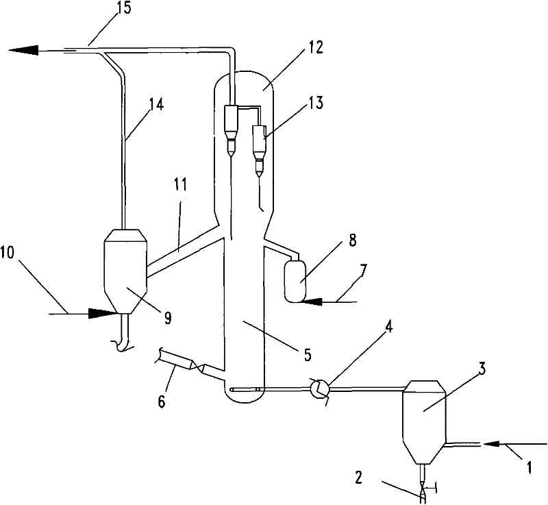
[0017] in such as figure 1 In the regeneration system shown, the catalyst is SAPO-34. After the regeneration air enters the dehydration area of ​​the regeneration medium for dehydration, it enters the regeneration area of ​​the regenerator after being heated to 155°C, and contacts with the carbon-deposited catalyst to generate flue gas and form a regeneration catalyst at the same time. After the flue gas is separated by the gas-solid cyclone separator, it enters the follow-up system through the flue gas pipeline, and the regenerated catalyst enters the degassing area, contacts with water vapor, removes the entrained flue gas and enters the reaction system, and the flue gas removed in the degassing area And the degassing medium enters the flue gas pipeline. The dehydration zone adopts silica gel drying method for dehydration. The carbon deposition mass fraction of the carbon deposition catalyst is 3.8%. A heat extraction zone is set outside the regenerator. The fluidized mediu...

Embodiment 2

[0019] According to the conditions and steps described in Example 1, the regeneration air enters the regeneration zone of the regenerator after being heated to 120° C., the mass fraction of the carbon deposition amount of the carbon deposition catalyst is 4.5%, the regeneration temperature is 685° C., and the regeneration pressure is 0.1 MPa. The linear velocity of the gas phase is 0.8 m / s, the partial pressure of water vapor in the regeneration zone of the regenerator is 19 kPa, and the catalyst content in the flue gas at the outlet of the gas-solid cyclone separator in the regenerator settling zone is 0.38 g / m 3 .

Embodiment 3

[0021] According to the conditions and steps described in Example 1, the regeneration air enters the regeneration area of ​​the regenerator after being heated to 142°C. The regeneration temperature is 630°C, the regeneration pressure is 0.2 MPa, and the gas phase velocity is 0.4 m / s. The partial pressure of water vapor in the area is 8.7 kPa, the mass fraction of carbon deposition in the carbon deposition catalyst is 2.9%, the fluidized medium in the hot area is air, and the dehydration area adopts 13X molecular sieve drying method for dehydration, and the gas-solid cyclone in the regenerator settlement area Catalyst content in flue gas at separator outlet is 0.16 g / m 3 .


PUM


Abstract

The invention relates to a method for reducing catalyst running loss in a methanol-to-olefins regeneration system, which mainly solves the problem of relatively large catalyst running loss in a regenerator in the prior art. The present invention adopts a method for reducing catalyst running loss in a methanol-to-olefins regeneration system, comprising the following steps: (a) providing a methanol-to-olefins regeneration system, including a regenerator regeneration zone, a regenerator settling zone, a heat extraction zone, Degassing area, regeneration medium dehydration area, flue gas pipeline; (b) The regeneration medium enters the regeneration area of ​​the regenerator after being dehydrated in the regeneration medium dehydration area, and contacts with the carbon deposition catalyst to generate flue gas and regeneration catalyst at the same time; (c) After the gas is separated by the gas-solid cyclone separator, it enters the follow-up system through the flue gas pipeline; (d) the regenerated catalyst enters the degassing area, removes the entrained flue gas and enters the reaction system, the flue gas removed in the degassing area and the degassing The technical proposal that the medium enters the flue gas pipe better solves the above problems and can be used in the industrial production of low-carbon olefins.

Description

technical field [0001] The invention relates to a method for reducing catalyst running loss in a methanol-to-olefin regeneration system. technical background [0002] Low-carbon olefins, namely ethylene and propylene, are two important basic chemical raw materials, and their demand is increasing. Generally, ethylene and propylene are produced through petroleum routes, but due to the limited supply and high price of petroleum resources, the cost of producing ethylene and propylene from petroleum resources continues to increase. In recent years, people have begun to vigorously develop the technology of converting alternative raw materials into ethylene and propylene. Among them, an important class of alternative raw materials for the production of light olefins are oxygenates, such as alcohols (methanol, ethanol), ethers (dimethyl ether, methyl ethyl ether), esters (dimethyl carbonate, methyl formate Esters), etc., these oxygenated compounds can be converted from coal, natur...

Claims


Application Information

Patent Timeline
IPC IPC(8): B01J38/12B01J29/90C07C1/20C07C11/04C07C11/06
CPCY02P20/52Y02P20/584Y02P30/20Y02P30/40
Inventor 齐国祯钟思青金永明陈伟
Owner CHINA PETROLEUM & CHEM CORP
Learn More