Side-pumped optical fiber structure and manufacturing method thereof

A technology for pumping optical fibers and manufacturing methods, which is applied in the direction of cladding optical fibers, manufacturing tools, and glass manufacturing equipment. Smaller area, improved pumping efficiency, and better operability

Active Publication Date: 2011-12-28
WUHAN YANGTZE SOTON LASER CO LTD
View PDF14 Cites 30 Cited by
  • Summary
  • Abstract
  • Description
  • Claims
  • Application Information

AI Technical Summary

Problems solved by technology

However, this method does not have good practical operability, and the more important problem is that because only equipment such as a tapered machine can be used to fuse and taper or thin multiple optical fibers, this method can only make very short lengths The optical c

Method used


Image

  • Side-pumped optical fiber structure and manufacturing method thereof
  • Side-pumped optical fiber structure and manufacturing method thereof
  • Side-pumped optical fiber structure and manufacturing method thereof

Examples


Embodiment 1

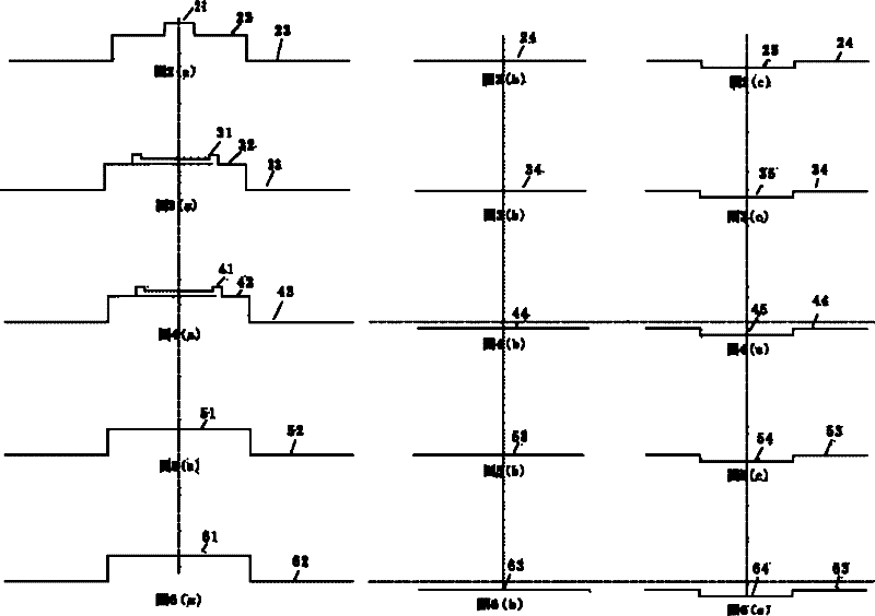
[0066] like Figure 2(a) ~ Figure 2(c) As shown, the refractive index distribution of the active optical fiber of this embodiment is shown in FIG. 2( a ), which is divided into three layers, and the core 21 is made of ytterbium-doped silica glass, which has the highest refractive index. Surrounding the core 21 is an annular inner cladding 22 of quartz glass doped with aluminum. The inner cladding 22 has a lower refractive index than the core 21 , and the difference between the two is 0.0007. The outermost outer cladding layer 23 is made of high-purity quartz glass, whose refractive index is lower than that of the inner cladding layer 22, and the difference between the two refractive indices is 0.004. Passive optical fiber 24 can be a single high-purity quartz glass material, and its refractive index is 1.4575, as shown in Figure 2 (b); it can also be a high-purity quartz glass material with a small amount of fluorine element doping 25, and its refractive index is 1.4572, as s...

Embodiment 2

[0082] like Figure 3(a) ~ Figure 3(c)As shown, other structures of this embodiment are the same as those of Embodiment 1, the only difference lies in the refractive index distribution and size parameters of the active optical fiber. As shown in Fig. 3 (a), this active optical fiber is also divided into three layers of core 31, inner cladding 32 and outer cladding 33, the refractive index of the center of the core 31 is uniform, and the refractive index of the edge of the core 31 is higher than that of the center of the core 31. The index is slightly higher, and the refractive index difference Δ between the two is 0.0002. This design can make the Gaussian energy distribution of the fiber core 31 expand to the edge of the fiber core 31 under high power working conditions, so that the laser energy is relatively evenly distributed in the fiber core 31 region, avoiding the fiber core 31 region. Central energy density is too high. like Figure 3(b) and 3(c) As shown, the refrac...

Embodiment 3

[0085] like Figure 4(a) ~ Figure 4(c) As shown, in this embodiment, the refractive index distribution of the active fiber is the same as that of the active fiber in Embodiment 2. The only difference is its passive optical fiber 44 . The refractive index of the passive optical fiber 44 is 1.4570, which is slightly lower than the refractive index of the glass material of the outer cladding 43 of the active optical fiber. The center of the passive optical fiber can also be a glass material with more fluorine element doping 45, and its refractive index is slightly 1.4565. . In this embodiment, the diameters of the active fiber and the passive fiber are both 250 μm. Wherein, the diameter of the core 41 of the active optical fiber is 25 μm, the numerical aperture of the inner cladding 42 relative to the core 41 is 0.02, and the numerical aperture of the outer cladding 43 relative to the inner cladding 42 is 0.04.

[0086] The preparation method of this embodiment is also the sam...


PUM

PropertyMeasurementUnit
Diameteraaaaaaaaaa
Diameteraaaaaaaaaa
Diameteraaaaaaaaaa

Abstract

A lateral pumped fiber structure comprises: at least one active optical fiber, which is used to generate laser or amplify the laser; at least one passive optical fiber, which is used to connect a pumping source. The active optical fiber and the passive optical fiber form an optical contact in a radial direction. The manufacturing method of the lateral pumped fiber structure comprises the following steps: 1) respectively preparing an active optical fiber performing rod and a passive optical fiber performing rod; 2) respectively performing wire drawing to the prepared active optical fiber performing rod and the passive optical fiber performing rod and making the active optical fiber and the passive optical fiber; 3) coupling at least one active optical fiber to at least one passive optical fiber so that the optical contact in a radial direction between the active optical fiber and the passive optical fiber can be formed. By using the fiber structure of the invention, pumping efficiency is high; a manufacturing technology and coupling equipment are simple; costs are low. The fiber structure of the invention is especially suitable for a high power optical fiber laser and an optical fiber amplifier.

Description

technical field [0001] The invention relates to a fiber laser and a fiber amplifier, in particular to a side-pumped fiber structure for the fiber laser and a fiber amplifier and a manufacturing method thereof. Background technique [0002] With the rapid development of high-power fiber coupling technology and pumping technology, high-power fiber lasers and high-power fiber amplifiers have made great progress in the fields of laser material processing, national defense and military, laser medical treatment, and scientific research, and have demonstrated a wide range of applications. The application prospect has become a research hotspot since the 21st century. At present, the output power of a single optical fiber is on the order of kilowatts. This technology includes pumping light source technology, power supply technology, thermal management technology, optical fiber technology, and very critical pumping technology. Among them, in addition to the pump light source technolo...

Claims


Application Information

Patent Timeline
IPC IPC(8): G02B6/24G02B6/02G02B6/036C03B37/02C03C25/10
Inventor 陈抗抗韦会峰
Owner WUHAN YANGTZE SOTON LASER CO LTD
Why Eureka
Try Eureka