Method for preparing aluminum/hydrogen peroxide monomer batteries

A single battery and hydrogen peroxide technology, applied in battery electrodes, regenerative fuel cells, circuits, etc., can solve the problems of low effective reaction area of ​​electrodes, low utilization rate of active materials, and lower specific energy of batteries, so as to improve effective reaction Effects of area, weight reduction, and specific energy improvement

Active Publication Date: 2012-02-01
CHINA ELECTRONIC TECH GRP CORP NO 18 RES INST
View PDF4 Cites 2 Cited by
  • Summary
  • Abstract
  • Description
  • Claims
  • Application Information

AI Technical Summary

Problems solved by technology

[0003] Aluminum/hydrogen peroxide batteries can be divided into single-chamber and double-chamber structures: the single-chamber battery has simple structure, low cost and high reliability, but due to Direct reaction, low utilization rate of active materials, which reduces the specific energy of the battery, so most of the current dual-chamber aluminum/hydrogen peroxide batteries are used; the dual-chamber structure of the battery separates the cathode area and the anode area through an ion exchange membrane to form a cathode chamber And the anode chamber can prevent the direct reaction between the aluminum electrode and the hydrogen peroxide electrode and improve the utilization rate of the active material. Since the battery needs to circulate the electrolyte to replenish the hydrogen peroxide consumed by the reaction and take away the reaction product and exhaust gas

Method used


Image

  • Method for preparing aluminum/hydrogen peroxide monomer batteries
  • Method for preparing aluminum/hydrogen peroxide monomer batteries
  • Method for preparing aluminum/hydrogen peroxide monomer batteries

Examples


Embodiment Construction

[0037] In order to further understand the invention content, characteristics and effects of the present invention, the following examples are given, and detailed descriptions are as follows in conjunction with the accompanying drawings:

[0038] Manufacturing process of the present invention:

[0039] Preparation of the anode part:

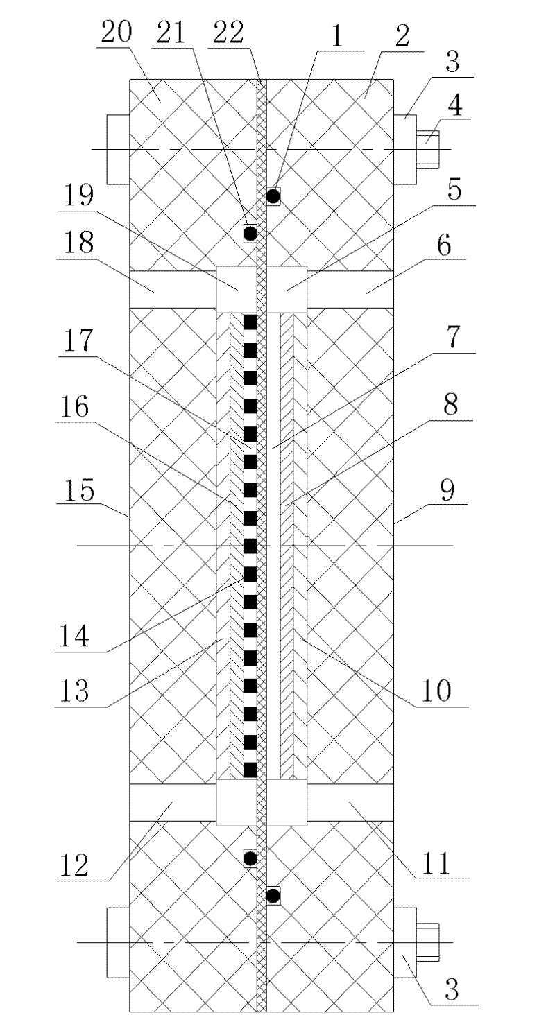
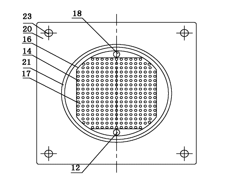
[0040] like image 3 As shown, first select an aluminum plate with a thickness of 0.5mm, square sides, and rounded corners, and connect the ends of the four rounded corners to form a round aluminum plate as the anode 16. The phenolic resin of 0.5mm, diameter 2mm is used as granular spacer 14, and the gap between granular spacers forms anode flow channel 17, selects the nickel plate with thickness 1mm, shape and size identical with anode as anode current collector 13; The 20mm square 3240 epoxy phenolic resin plate is used as the anode end plate 20, and an anode groove 19 with a depth of 2mm is processed at the center of the anode end plate. The ...


PUM


Abstract

The invention discloses a method for preparing aluminum/hydrogen peroxide monomer batteries, and the method is used for hermetically and fixedly assembling an anode part and a cathode part into an integral monomer battery, wherein the anode part and the cathode part are successively prepared; and the method is characterized in that granular spacers are fully adhered to one surface of the anode part at a certain interval, and the interval is used as an anode channel; and a through trough is pressed on one surface of a cathode substrate of the cathode part and used as a cathode channel. In the invention, an anode channel is formed by using granular spacers, thereby reducing the weight of the battery, reducing the pressure loss of an electrolyte flowing through the anode part, better facilitating the discharge of hydrogen and reaction products AlO2<->, and improving the specific energy and energy density of the battery; a cathode channel is pressed on the cathode part so as to form a catalyst layer-flow field plate two-in-one structure, thereby reducing the thickness and weight of the battery; an oxidizing agent can directly flow in the three-dimensional catalyst layer, and the mass transfer of hydrogen peroxides is smooth, thereby improving the specific energy of the battery; and an ion exchange membrane achieve an effect of transformation between a double chamber structure and a single chamber structure of the battery, and is suitable for energy type power battery packs of low speed underwater equipment.

Description

technical field [0001] The invention relates to the technical field of underwater power batteries, in particular to a preparation method of an aluminum / hydrogen peroxide single battery. Background technique [0002] Aluminum / hydrogen peroxide battery is an energy-type chemical power source developed in recent years. This battery has the characteristics of high specific energy and is suitable for underwater work. The metal / hydrogen peroxide fuel cells with Mg and Al as anodes, Al-H 2 o 2 The battery has been applied to underwater equipment, and the specific energy can reach 200Wh / kg-240Wh / kg. [0003] Aluminum / hydrogen peroxide batteries can be divided into single-chamber and double-chamber structures: the single-chamber battery has simple structure, low cost and high reliability, but due to Direct reaction, low utilization rate of active materials, which reduces the specific energy of the battery, so most of the current dual-chamber aluminum / hydrogen peroxide batteries ar...

Claims


Application Information

Patent Timeline
IPC IPC(8): H01M8/18H01M4/88
CPCY02E60/528Y02E60/50
Inventor 段然王宇轩黄雯
Owner CHINA ELECTRONIC TECH GRP CORP NO 18 RES INST
Why Eureka
Try Eureka