Sintering ore cooling device and waste heat recovery system thereof

A technology for sintering and waste heat, which is applied in steam engine installations, waste heat treatment, lighting and heating equipment, etc. It can solve the problems of large one-time investment, large floor space, high operation and maintenance costs, and achieve the effect of high heat exchange efficiency.

Inactive Publication Date: 2012-02-08
刘柏谦
View PDF4 Cites 42 Cited by
  • Summary
  • Abstract
  • Description
  • Claims
  • Application Information

AI Technical Summary

Problems solved by technology

The use of the above three cooling methods not only occupies a large area and requires a large investment, but also requires high operation and maintenance costs. Small and medium-sized iron and steel enterprises can only stay away from it.

Method used


Image

  • Sintering ore cooling device and waste heat recovery system thereof
  • Sintering ore cooling device and waste heat recovery system thereof
  • Sintering ore cooling device and waste heat recovery system thereof

Examples


Embodiment 1

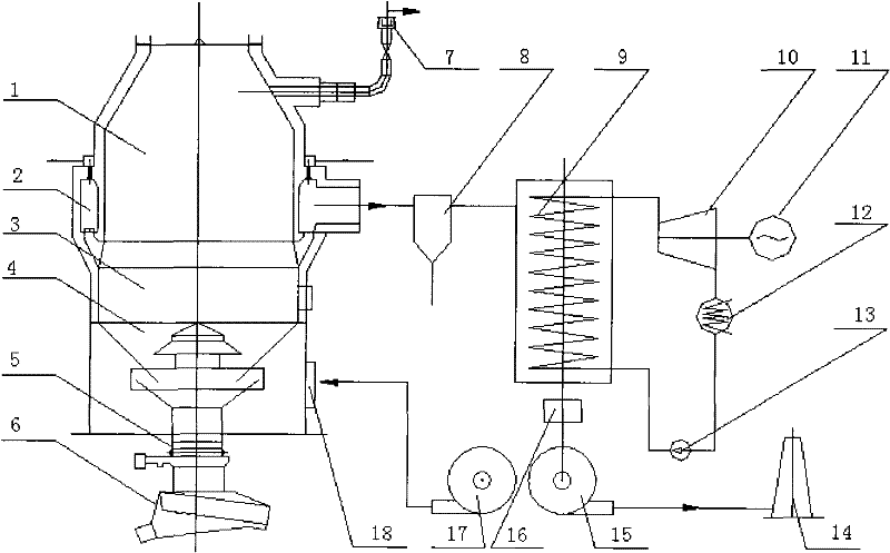
[0028] The temperature of the sinter leaving the sintering machine is 700-750°C. The design parameters are sintered ore 50t / h, 700℃. The heat dissipation of the cold ore furnace body is considered at 4%, and the cooling medium can obtain 7520kW of heat. 7520kW can drive 37054m of cold air at 20°C 3 / h heated to 550°C. The 550°C hot air heats the steam from the waste heat boiler to the design steam parameters and consumes 773kW. The cooled air is 500°C, which is used as the heat source of the waste heat boiler. 500°C air from waste heat boiler superheater and 235°C air from sintering machine 77111m 3 / h after mixing, it enters the evaporation part of the waste heat boiler, and heats water at 20°C to 2.5MPa saturated steam at 223.9°C. The 150°C medium after heat release is discharged into the atmosphere. The total air volume flowing through the heat exchanger is 114165m 3 / h.

[0029] The running time of the sintering machine and the cold ore furnace is 7680 hours (runni...

Embodiment 2

[0032]The temperature of sinter leaving the sintering machine is considered to be 500-600°C. The design parameters are sintered ore 50t / h, 550℃. The heat dissipation of the cold ore furnace body is considered at 4%, and the heat that can be recovered by sintering is 4472kW. Use 300°C sintering waste gas to increase the cold air from 20°C to 150°C and send it to the cold ore furnace to recover the heat of sintering ore. The required air volume is 45,000 cubic meters per hour. The heating surface of the waste heat boiler is divided into three parts. The first part raises the cold water from 20°C to 150°C to become hot water; the second part heats the 150°C hot water to the saturated steam temperature of 224°C under the pressure of 2.5MPa; the third part realizes steam superheating. Since the heat of sintered ore is not enough to realize the above process, 3278kW of additional heat is required, and 3380Nm3 / h of blast furnace gas of 3500kJ / Nm3 is required.

[0033] Cold air an...


PUM


Abstract

The invention relates to the physical heat recovery field of solid high temperature materials. The system can be applied in the waste heat recovery of extra-large high-temperature particles such as high-temperature sintering ore and the like and the process is as follows: the high-temperature sintering ore from a sintering machine falls into a cold sinter furnace through a feeding system, gradually falls with ore discharge and enters a cooling section to radiate heat. The cooled sintering ore enters a vibrator feeder discharging system through a blanking hopper and a regulating gate. The process can be adopted to cool the sintering ore from about 700-800 DEG C to about 100 DEG C. Cold air provided by an air blower enters the cold sinter furnace through an air inlet and a blast cap, absorbs heat in the cooling section and then enters an annular channel, the high-temperature gas from the annular channel enters a waste heat boiler through a dust remover, the heat is transferred to a working medium and then pumped by the draft fan through the dust remover, and the gas is discharged in a chimney when reaching the dedusting standard. The heat-absorbing working medium (usually water) is converted to superheated steam with a certain parameter in the waste heat boiler to do work in a turbine and drive a generator to generate power. Dead steam after doing work enters a condenser and is sent back to the waste heat boiler through a circulating water pump, thus, a thermal cycle is completed.

Description

technical field [0001] The invention relates to high-temperature sinter cooling equipment and a waste heat recovery system. The cooling process and waste heat recovery system are simple and inexpensive, and can replace traditional equipment such as ring coolers and belt coolers. Background technique [0002] It is estimated that China's steel output will reach 630 million tons in 2010. The direct raw material for iron and steel metallurgical production is iron ore, and iron ore processing is the upstream process of iron and steel production. In fact, in the iron and steel metallurgy process, the iron ore sintering process is one of the main energy-consuming processes in iron and steel production. Z.C.Guo et al (2009, Energy (2009), doi:10.1016 / j.energy.2009.04.008), Bao Weijun, etc. (Second National Symposium on Circular Economy and Ecological Industry), Cai Jiuju, etc. (Cai Jiuju et al., Iron and Steel, Vol. 42, No. 6, June 2007), Guo Hanjie et al. (Guo Hanjie et al., Ir...

Claims


Application Information

Patent Timeline
Patent Type & Authority Applications(China)
IPC IPC(8): F27D15/02F27D17/00F01D15/10F01K11/02
CPCY02P10/25
Inventor 刘柏谦
Owner 刘柏谦
Why Eureka
Try Eureka