Biodegradable stent with groove and preparation method thereof

A biodegradable material technology, applied in the field of biodegradable stents with grooves and its preparation, can solve the problems of smooth muscle cell proliferation, arterial wall necrosis, stent stenosis, etc., and achieve short heating time, controllable temperature and safety high effect

Active Publication Date: 2012-03-21
SHANGHAI MICROPORT MEDICAL (GROUP) CO LTD
View PDF7 Cites 23 Cited by
  • Summary
  • Abstract
  • Description
  • Claims
  • Application Information

AI Technical Summary

Problems solved by technology

The disadvantage of this method is that the balloon exposed at both ends of the stent directly contacts the vessel wall at high temperature (65°C-70°C for a few seconds), resulting in necrosis of the artery wall, and the ensuing complication is the proliferation of smooth muscle cells, which leads to in-stent restenosis

Method used


Image

  • Biodegradable stent with groove and preparation method thereof
  • Biodegradable stent with groove and preparation method thereof
  • Biodegradable stent with groove and preparation method thereof

Examples


Embodiment 1

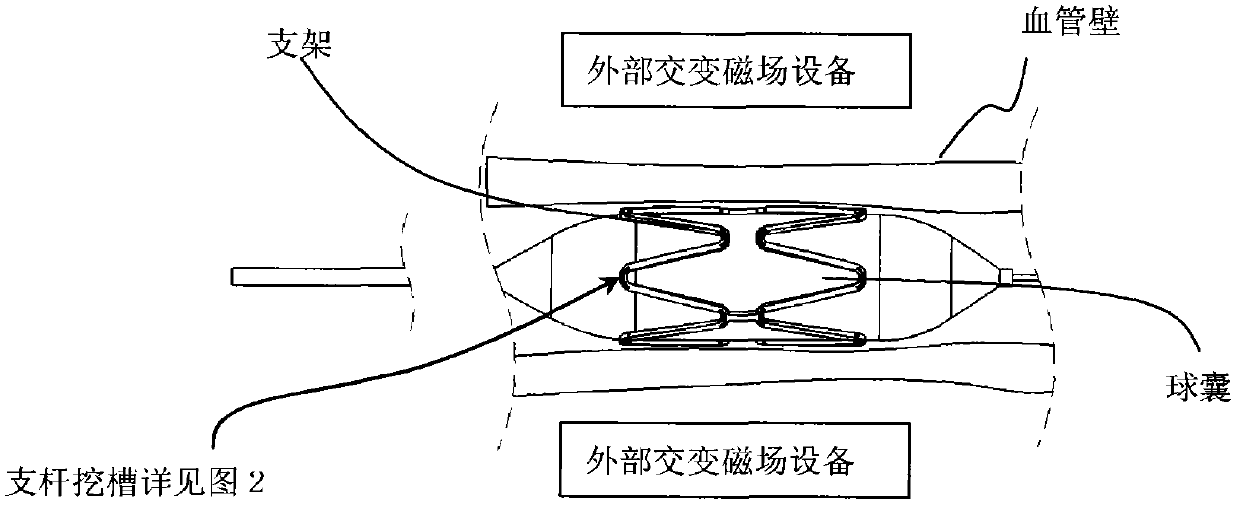
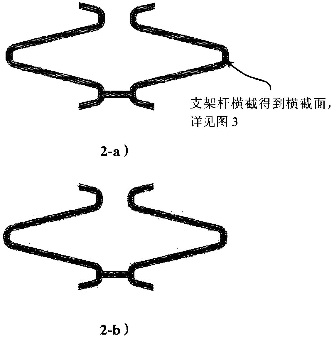
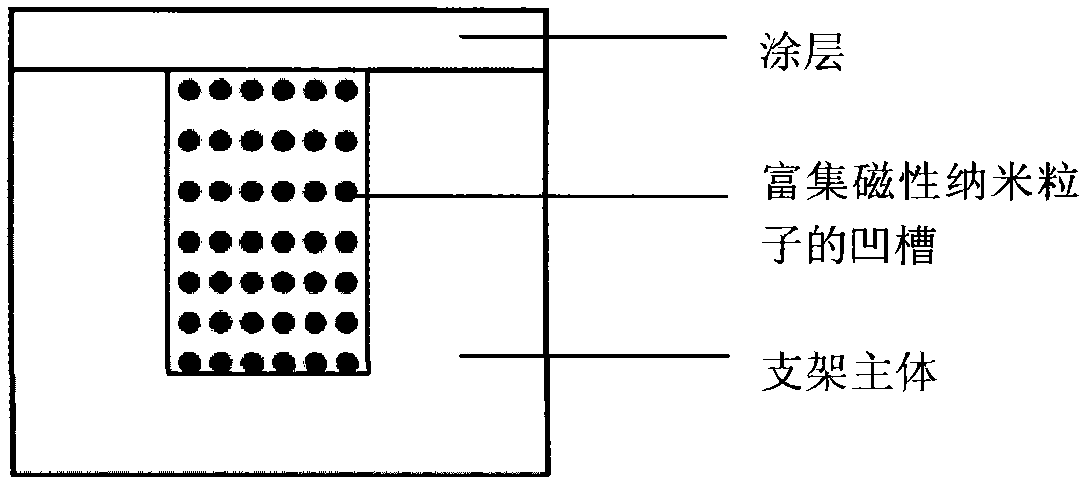
[0027] See attached figure 2-a), Extrude the L-lactic acid-caprolactone copolymer (PLCA) material to obtain a pipe with an outer diameter of 2.5mm, and then process it into a stent by laser engraving technology to obtain the stent main body; dig 150 μm deep at the reinforcement ring of the stent main body , a groove with a width of 150 μm; the γ-Fe with a particle size of 80 nm 2 o 3 The magnetic nanoparticles are made into a magnetic fluid with anhydrous ethanol solvent, which is added dropwise into the aforementioned groove, and the mass of the nanoparticles accounts for 1 / 20 of the weight of the stent; after the solvent is completely evaporated, the outer surface of the main body of the stent is sprayed with rapamycin (Rapamycin) and its derivatives polymeso-lactic acid (PDLLA) material forms the outer coating of the stent. The cross section of the bracket is as image 3 Shown, reflecting the structure of the scaffold. The stent includes a main body structure, grooves ...

Embodiment 2

[0030] See attached figure 2 -b), using a laser cutting machine to process the main body of the stent on a poly-L-lactic acid (PLLA) tube with an outer diameter of 3.0mm; The MnFeO magnetic nanoparticles and PLLA are dissolved in the solvent tetrahydrofuran, and the solution is sprayed into the groove of the stent. After the solvent volatilizes completely, the weight of the nanoparticles in the stent accounts for 1 / 10 of the weight of the stent; the outer surface of the stent body is sprayed with Rapa The L-lactic acid and glycolide copolymer (PLGA) material of Rapamycin forms the outer coating of the stent. The cross section of the bracket is as image 3 Shown, reflecting the structure of the scaffold. The stent includes a main structure, grooves enriched with magnetic nanoparticles and an outer coating; the grooves are distributed in all parts of the stent including the deformed parts.

[0031] The stent is crimped onto the delivery system and packaged for sterilization....


PUM

PropertyMeasurementUnit
widthaaaaaaaaaa
thicknessaaaaaaaaaa
widthaaaaaaaaaa

Abstract

The invention relates to the field of medical apparatuses, in particular to a biodegradable polymer stent with grooves and a preparation method thereof. The biodegradable polymer stent comprises a stent main body, magnetic nano particles and a coating layer, wherein the grooves are excavated at parts bearing stent deformation or all parts of the stent main body, and the magnetic nano particles are arranged in the grooves. The temperature of the magnetic nano particles is increased through an external alternating magnetic field to heat the stent. After the stent is heated and expanded, the stent is cooled, fixed and formed in a body, the retraction rate can be decreased to less than 10 percent, and the consequences such as collapse, displacement and the like are avoided. At the same time, by heating the stent through the magnetic nano particles, the thermal damages to the wall of a blood vessel can be minimized.

Description

technical field [0001] The invention relates to the field of medical instruments. More specifically, the present invention relates to a grooved biodegradable stent and its preparation method. Background technique [0002] With the gradual deepening of the research on biodegradable materials, its performance in various aspects is more suitable for the preparation of new biodegradable scaffolds. At present, quite a few research institutions are conducting the development and experiments of biodegradable scaffolds. Some clinical data show that biodegradable stents have good clinical effects and are gradually approaching metal stents in terms of physical properties and delivery performance. Compared with metal stents, biodegradable stents have better biocompatibility, drug-loading performance, and gradually degrade after treatment, so they have great potential and development prospects (References 1, 6-7 and 9). [0003] Restricted by the shape and diameter of the coronary art...

Claims


Application Information

Patent Timeline
Patent Type & Authority Applications(China)
IPC IPC(8): A61F2/90A61F2/94A61L31/14A61L31/06
CPCA61F2/91A61F2210/0004A61F2210/009A61L31/08A61L31/148A61L2400/12
Inventor 黄楚波石秀凤罗七一田浩王一涵
Owner SHANGHAI MICROPORT MEDICAL (GROUP) CO LTD
Why Eureka
Try Eureka