
Implanted photoelectrode collecting, regulating and controlling device

A control device and photoelectrode technology, applied in the field of medical devices, can solve the problems of unadjustable, fixed position, unable to adapt to light control and electrophysiological measurement, etc., and achieve high flexibility, high spatial resolution, and meet the needs of research and treatment desired effect

Active Publication Date: 2012-03-21
SHENZHEN INST OF ADVANCED TECH CHINESE ACAD OF SCI
View PDF1 Cites 29 Cited by
  • Summary
  • Abstract
  • Description
  • Claims
  • Application Information

AI Technical Summary

Problems solved by technology

[0004] However, limited by the current manufacturing technology of microelectrodes and optical fibers, traditional implantable photoelectrodes have many shortcomings. For example, the positions of optical fibers and electrodes in traditional photoelectrodes are fixed and cannot be adjusted according to actual needs. Light regulation and electrophysiological measurement adapted to complex living environment

Method used


Image

  • Implanted photoelectrode collecting, regulating and controlling device
  • Implanted photoelectrode collecting, regulating and controlling device
  • Implanted photoelectrode collecting, regulating and controlling device

Examples


Embodiment 1

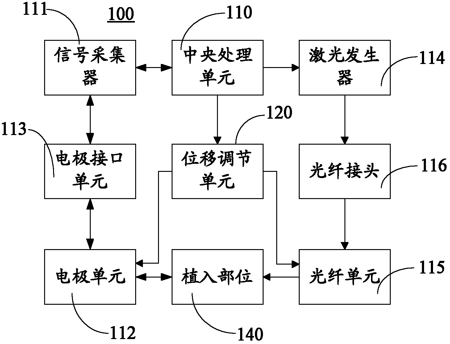
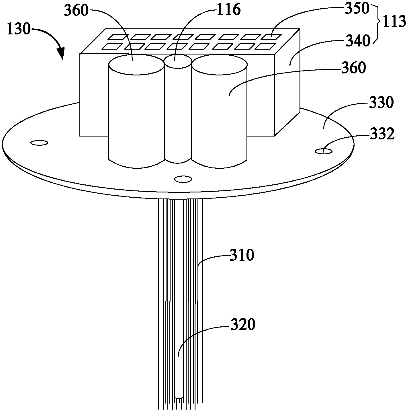
[0042] Please combine figure 1 , figure 2 and image 3 , the electrode unit 112 of this embodiment is an electrode array including 16 needle-shaped microelectrodes 310 . The fiber optic unit 115 includes an optical fiber 320 .

[0043] The electrode interface unit 113 includes an electrode holder 340 fixed on the base fixing plate 330 and an insertion hole 350 opened on the electrode holder 340 . The signal collector 111 is provided with a plug (not shown) adapted to the jack 350 . The signal collector 111 is connected to the electrode unit 112 through a plug inserted into the socket 350 .

[0044] The base fixing plate 330 is disc-shaped, on which there are fixing holes 332 for fixing the photoelectrode acquisition control unit 130 on the implantation site (such as the skull). The electrode holder 340 , the optical fiber connector 116 and the micro stepper motor 360 are fixed on one side of the base fixing plate 330 . Two micro stepping motors 360 are used to adjust th...

Embodiment 2

[0049] Please combine figure 1 , figure 2 and Figure 8 The structure of the photoelectrode collection control unit 130 in this embodiment is basically the same as that in Embodiment 1, except that the microelectrode 810 in this embodiment is a disk-shaped electrode. The microelectrode 810 is arranged on the electrode fixing plate 820 , and the distance between the microelectrode 810 and the base fixing plate 830 is greater than the distance between the free end of the optical fiber 840 and the base fixing plate 830 . The electrode fixing plate 820 is arranged parallel to the optical fiber 840 . The end of the electrode fixing plate 820 adopts a point setting, which is convenient for implantation.

[0050] In other embodiments, in order to further increase the strength and accuracy of the collected signal, multiple electrode fixing plates 820 can be arranged in parallel, such as Figure 9 shown.

[0051] By combining microelectrodes, optical fibers and micro stepping mot...


PUM


Abstract

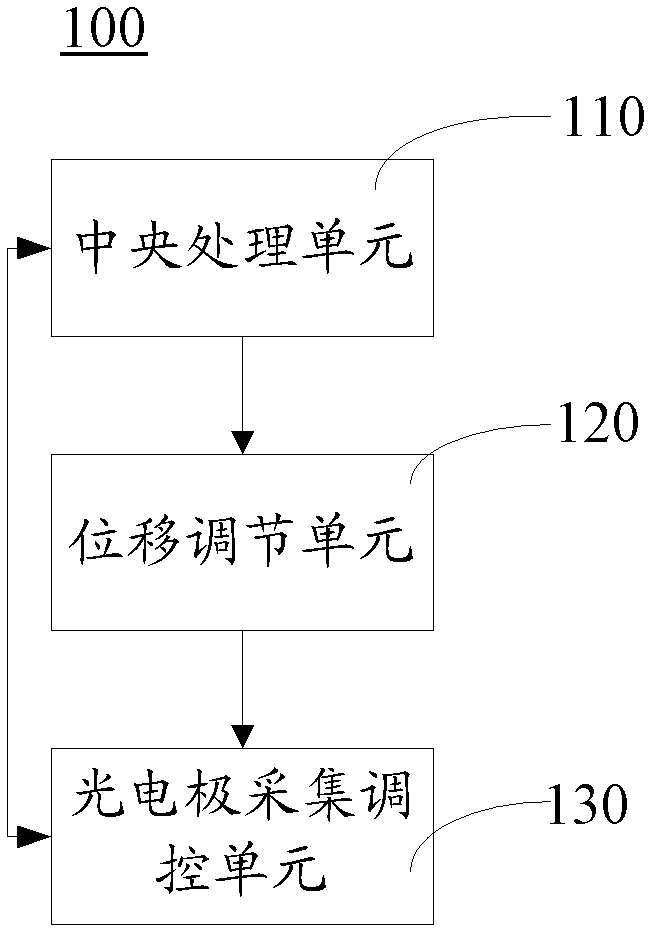
The invention relates to an implanted photoelectrode collecting, regulating and controlling device, which comprises a central processing unit, a displacement regulating unit and a photoelectrode collecting, regulating and controlling unit. The central processing unit is used for controlling the displacement regulating unit and the photoelectrode collecting, regulating and controlling unit; the displacement regulating unit is used for regulating the implantation depth of the photoelectrode collecting, regulating and controlling unit; and the photoelectrode collecting, regulating and controlling unit is used for carrying out light regulation and control and the collection of a physiological signal on an implantation position and feeding back the collected physiological signal to the central processing unit. According to the implanted photoelectrode collecting, regulating and controlling device, an electrode unit and a fiber unit are combined together to form a photoelectrode array; furthermore, the electrode unit and the fiber unit are respectively controlled by utilizing the displacement regulating unit; the implantation depths and positions of the electrode unit and the fiber unit are regulated according to the body environment of an organism; the flexibility is high; the more accurate, more effective, high-spatial-resolution and long-term light regulation and control and the electrophysiological record of the implantation position can be achieved; and the requirements on the research and the treatment of a nervous system and a mental disease are met.

Description

【Technical field】 [0001] The invention relates to the field of medical equipment, in particular to an implantable photoelectrode acquisition and control device. 【Background technique】 [0002] Epilepsy, Parkinson's disease, schizophrenia, anorexia nervosa, depression, Alzheimer's disease, tremors, convulsions, obsessive-compulsive disorder, anxiety, stroke, and drug addiction and many other central nervous system and mental diseases have been threatening human health , bothering the normal life of human beings. At present, there are about 600 million people with nervous system and mental diseases in the world, of which my country accounts for about a quarter. And with the aging of society and the influence of various factors such as economy and environment, the number of patients with these diseases is increasing year by year, which has caused huge obstacles to the development of society and economy. Therefore, there is an urgent need for a method to deeply study the remod...

Claims


Application Information

Patent Timeline
Patent Type & Authority Applications(China)
IPC IPC(8): A61N5/067A61B5/04A61B5/00
Inventor 鲁艺王立平李艳玲蔚鹏飞刘楠
Owner SHENZHEN INST OF ADVANCED TECH CHINESE ACAD OF SCI
Learn More