

Three-step variable-temperature diffusion process for silicon cell
A crystalline silicon cell, diffusion process technology, applied in diffusion/doping, circuit, crystal growth and other directions, can solve problems affecting cell efficiency, low cell open-circuit voltage and short-circuit current, poor ohmic contact, etc., to enhance blue light response, The effect of increasing knot depth
- Summary
- Abstract
- Description
- Claims
- Application Information
AI Technical Summary
Problems solved by technology
Method used
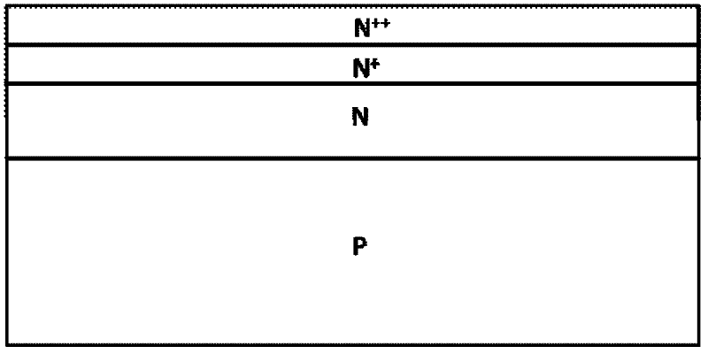
Image

Examples
Embodiment 1
[0023] Insert the textured polysilicon wafer into the quartz boat and put it on the boat. After entering the boat, raise the furnace temperature to 800°C. After the temperature stabilizes, 5 slm of large nitrogen, 0.8 slm of small nitrogen, and 0.3 slm of oxygen are introduced for low-temperature pre-deposition. The deposition time is 20 minutes. Then the temperature of the furnace was raised to 830°C, and 6slm of large nitrogen was introduced to carry out high-temperature push-in junction, and the push-in time was 10 minutes. Then the temperature of the furnace was raised to 850° C., and 5.5 slm of large nitrogen, 1.0 slm of small nitrogen, and 0.3 slm of oxygen were introduced for redeposition and diffusion. Finally, the temperature was lowered to 830°C, and 6 slm of large nitrogen was introduced to purge, and the boat was unloaded.
Embodiment 2
[0025] Insert the textured monocrystalline silicon wafer into the quartz boat and put it on the boat. After entering the boat, raise the furnace temperature to 780°C. After the temperature stabilizes, 5 slm of large nitrogen, 1.0 slm of small nitrogen, and 0.3 slm of oxygen are introduced for low-temperature pre-deposition. The deposition time is 15 minutes. Then the temperature of the furnace was raised to 820°C, and 6slm of large nitrogen was introduced to carry out high-temperature push-in junction, and the push-in time was 15 minutes. Then the furnace temperature was raised to 860°C, and 5.5 slm of large nitrogen, 0.5 slm of small nitrogen, and 0.2 slm of oxygen were introduced for redeposition and diffusion. Finally, the temperature was lowered to 830°C, and 6 slm of large nitrogen was introduced to purge, and the boat was unloaded.
PUM
 Abstract
Description
Claims
Application Information