Optical receiver uplink laser control circuit transformed by wired television bilateral network

A two-way network and cable TV technology, applied in the optical receiver uplink laser control circuit, hybrid optical fiber coaxial cable network two-way network transformation, based on the field of cable TV two-way transmission equipment, can solve the difficulty and cost of increased maintenance, complex network structure And other issues

Active Publication Date: 2012-03-21
CHANGSHU GAOSHIDA PHOTOELECTRICITY TECH
View PDF4 Cites 1 Cited by
  • Summary
  • Abstract
  • Description
  • Claims
  • Application Information

AI Technical Summary

Problems solved by technology

Although the technical standards and products are relatively mature, due to the complex network structure, a large number of optical nodes and radio frequency (RF) amplifiers, the difficulty and cost of network design, construction and maintenance are greatly increased

Method used


Image

  • Optical receiver uplink laser control circuit transformed by wired television bilateral network
  • Optical receiver uplink laser control circuit transformed by wired television bilateral network

Examples


Embodiment Construction

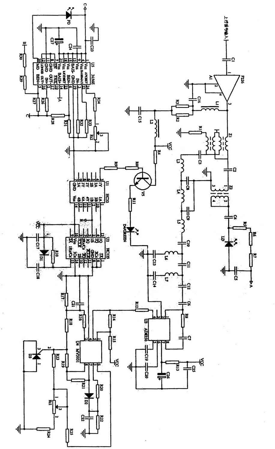
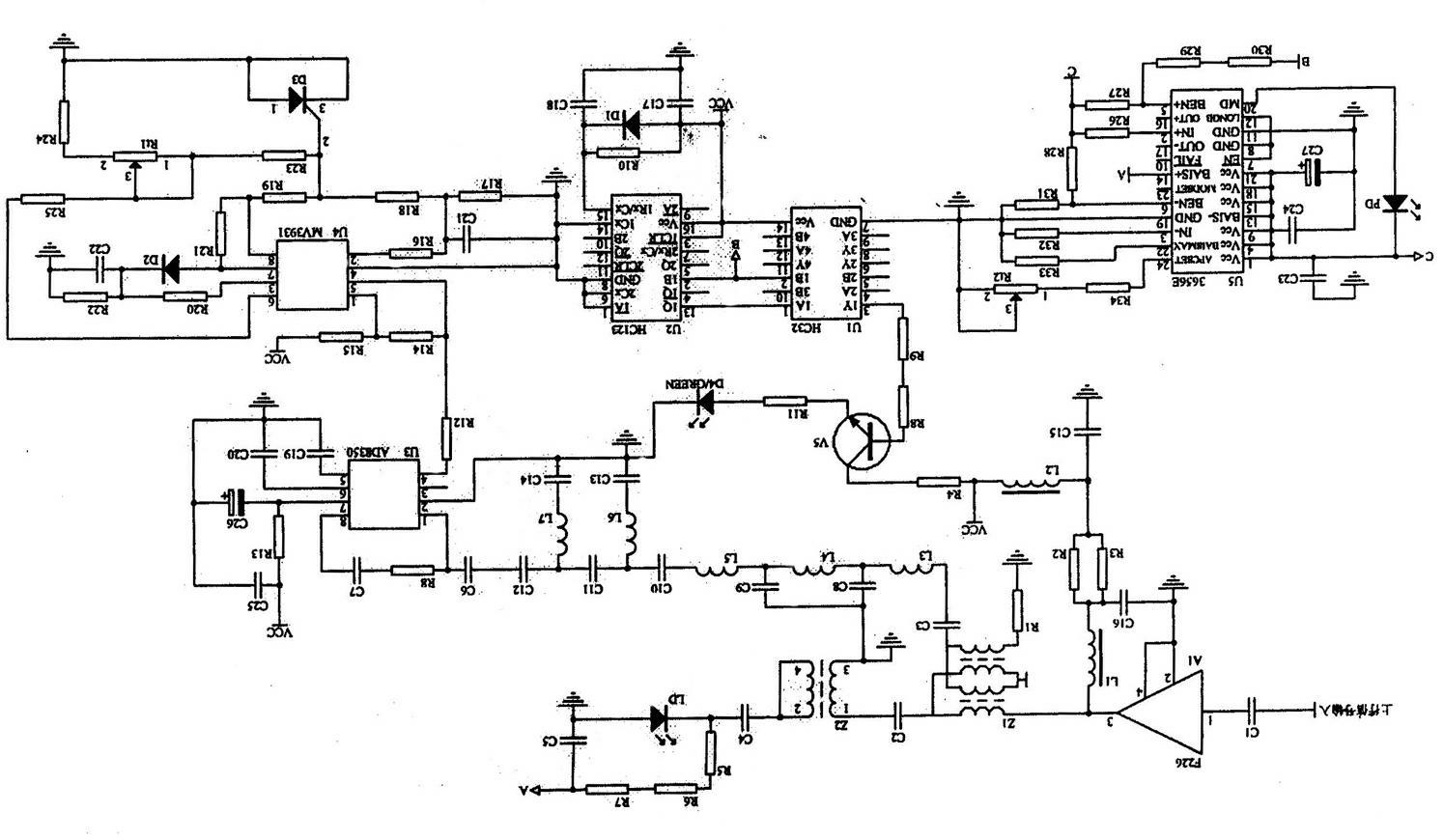
[0008] Refer to the figure: The uplink laser control circuit of the RFoG optical receiver is the uplink signal input amplifier tube, the amplifier tube amplifies the signal input to the main input terminal of the branch coil, and the output signal from the main output terminal of the branch coil goes to the uplink laser one way, and the other way to the burst laser drive circuit , the branch output terminal of the branch coil outputs the signal to the amplifying circuit through the low-pass filter circuit, the output signal of the amplifying circuit goes to the comparison circuit, the output signal of the comparison circuit goes to the monostable trigger circuit, the monostable trigger circuit and the double-input OR gate circuit, burst mode The laser drive circuit is connected to control the laser on and off to complete the control of the uplink laser.

[0009] Uplink signal input capacitor C1 to the amplifier tube A1, the power supply circuit is composed of inductors L1, L...


PUM


Abstract

The invention relates to an optical receiver uplink laser control circuit transformed by a wired television bilateral network, belonging to the technical field of wired television. The optical receiver uplink laser control circuit comprises an amplifier tube A1, a double input or gate chip U1, a trigger U2, an amplifying chip U3, a low voltage comparator U4, a driving chip U5, a branch coil Z1, a matching coil Z2, lasers LD and PD, inductors L1-L7, a transistor V1, diodes D1 and D2, a silicon controlled rectifier D3, a light-emitting diode D4, resistors R1-R34, capacitors C1-C27 and adjustable potentiometers Rt1 and Rt2, wherein A1 is an F226 amplifier tube produced by a British company OEI, U1 is an HC32 double input or gate chip, U2 is an HC123 trigger, U3 is an AD8350 amplifying chip, U4 is an MV3931 low voltage comparator, and U5 is a 3656E driving chip. The optical receiver uplink laser control circuit provided by the invention has the advantages of less noise convergence interference, accordance with IP-trend transformation, lower household average cost and high safety and reliability.

Description

technical field [0001] The invention relates to an uplink laser control circuit of an optical receiver for transformation of a bidirectional network of cable television, belonging to the technical field of cable television, in particular to a bidirectional transmission device based on cable television for transformation of a bidirectional network of a hybrid optical fiber coaxial cable network. The optical receiver of the present invention is a Radio Frequency over Fiber (RFoG) optical receiver. Background technique [0002] Since the day it was born, CATV (Cable Television) has never faced challenges and development opportunities like it does today. The core business of CATV faces direct competition from IPTV and satellite live broadcast, and its users are no longer satisfied with passively watching programs. , put forward diversified interactive entertainment requirements; the development of domestic digital TV in recent years has brought unprecedented development opportun...

Claims


Application Information

Patent Timeline
Patent Type & Authority Applications(China)
IPC IPC(8): H04B10/148H04B10/158H04N7/22H04B10/60
Inventor 叶黎达袁发农章冠华刘诚
Owner CHANGSHU GAOSHIDA PHOTOELECTRICITY TECH
Why Eureka
Try Eureka