
Airborne SAR (synthetic aperture radar) imaging method suitable for large squint angle

An imaging method and oblique angle of view technology, applied in the field of remote sensing image processing, can solve problems such as difficulty in ensuring image quality, image phase distortion, and difficulty in reducing two-dimensional coupling

Inactive Publication Date: 2012-03-28
SHANGHAI UNIV
View PDF0 Cites 27 Cited by
  • Summary
  • Abstract
  • Description
  • Claims
  • Application Information

AI Technical Summary

Problems solved by technology

[0004] When looking sideways, the RD imaging method can better realize the airborne SAR signal processing. The main disadvantage is that interpolation is required for distance migration correction. The phase distortion, especially the phase distortion is not allowed in some occasions
The Chirp Scaling imaging method utilizes the characteristics of the chirp signal emitted by the radar, introduces the chirp signal into the R-D domain of the radar echo, and corrects the distance migration trajectory at different distances to be the same as the trajectory at a certain reference distance. The frequency domain simultaneously completes range migration correction, distance compression and secondary distance compression, which avoids the interpolation operation and greatly improves the calculation efficiency. Difficult to guarantee quality

Method used


Image

  • Airborne SAR (synthetic aperture radar) imaging method suitable for large squint angle
  • Airborne SAR (synthetic aperture radar) imaging method suitable for large squint angle
  • Airborne SAR (synthetic aperture radar) imaging method suitable for large squint angle

Examples


Embodiment Construction

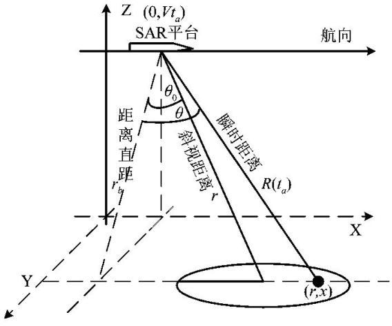
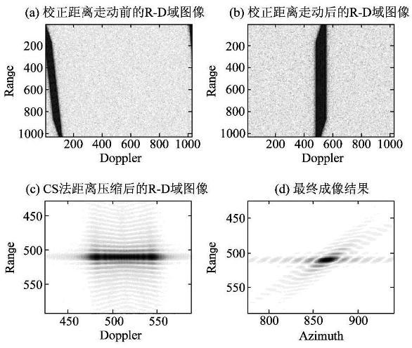
[0077] The effectiveness of the signal processing method is verified by processing the point target echo signal of the present invention in combination with specific radar parameters.

[0078] Table 1 gives the basic parameters of the radar

[0079] parameter value Flight speed of SAR platform (m / s) 250 The squint distance between the antenna and the center of the scene zone r(Km) 13 carrier frequency (GHz) 10 pulse width (s) bandwidth (MHz) 100 Frequency repetition period T(s) Synthetic aperture length l(m) 300

[0080] Carry out imaging processing on the echo signals of point targets and lattice targets respectively according to the following steps, and the imaging processing uses the software matlab to carry out simulation processing.

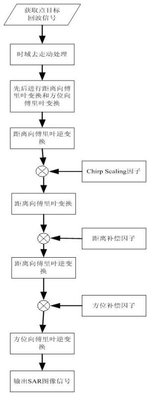
[0081] like figure 2 Shown, a kind of airborne SAR imaging method that is applicable to large oblique viewing angle of the present invention, the concrete steps of thi...


PUM


Abstract

The invention discloses an airborne SAR (synthetic aperture radar) imaging method suitable for a large squint angle. The method comprises the following steps of: (1) establishing an echo signal model; (2) performing signal imaging by the steps of: (2-1) performing distance fast Fourier transform and azimuth fast Fourier transform on a point target signal; (2-2) performing distance inverse Fouriertransform and performing accurate treatment on the phase of the signal; (2-3) multiplying the result by a Chirpscaling factor; (2-4) performing distance Fourier transform; (2-5) multiplying the result by a distance compensation factor; (2-6) performing distance inverse Fourier transform; (2-7) multiplying the result by an azimuth compensation factor; and (2-8) performing azimuth inverse Fourier transform to obtain a compressed SAR image signal. In the method, by imaging the point target under a large squint angle, a good peak-sidelobe ratio and an integral-sidelobe ratio can be obtained; a relatively high spatial resolution can be obtained in the distance direction and azimuth direction by use of the SAR pulse compression technology and the synthetic aperture technology; and moreover, themethod performs distance relocation correction in a time domain, simplifies an echo signal distance model, reduces the two-dimensional coupling quantity, adopts accurate phase unwrapping, realizes accurate correction of the signal and has a relatively high processing speed.

Description

technical field [0001] The invention relates to an airborne SAR imaging method suitable for large oblique viewing angles, and belongs to the technical field of remote sensing image processing. Background technique [0002] The emergence of the concept of "synthetic aperture" can be traced back to the 1950s. In June 1951, Carl Wiley of Goodyear Corporation of the United States proposed to improve the angular resolution of radar by frequency analysis, and developed a "Doppler beam sharpening" system in 1952. The system is the initial model of the synthetic aperture radar (SAR). While working with Carl Wiley, the Control Systems Laboratory of the University of Illinois began to independently study the synthetic aperture radar (SAR), and it was confirmed that the frequency analysis method can indeed improve the radar angular resolution. [0003] In July 1953, the first synthetic aperture radar image was obtained. At the summer seminar held at the University of Michigan in 195...

Claims


Application Information

Patent Timeline
IPC IPC(8): G01S13/90
Inventor 谢亚楠万智龙郑和刘文渊周洁
Owner SHANGHAI UNIV
Learn More