Grinding Wheel
A grinding wheel and abrasive tool technology, applied in abrasives, bonded grinding wheels, electrical components, etc., can solve problems such as cracks and quality degradation
- Summary
- Abstract
- Description
- Claims
- Application Information
AI Technical Summary
Problems solved by technology
Method used
Image
Examples
Embodiment 1
[0049] The resin bond composed of phenolic resin is mixed with diamond abrasive grains with a particle size of 5 μm at a volume ratio of 10% to 20%, and B with a particle size of 1 μm at a volume ratio of 45% to 20%. 4 C particles, and shaped into a cuboid shape. It was sintered at a sintering temperature of 180° C. for about 8 hours to form a resin bonded abrasive tool.
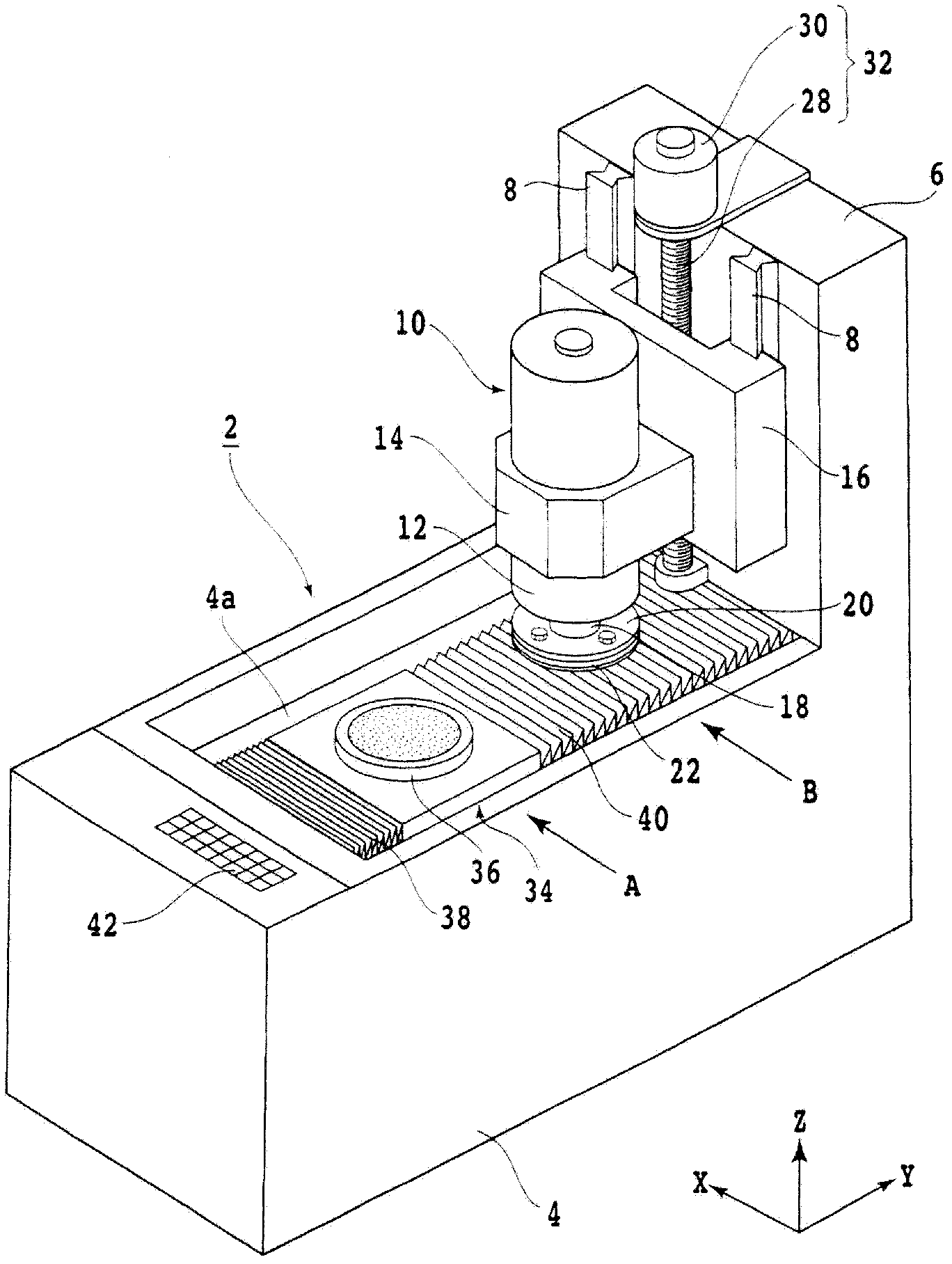
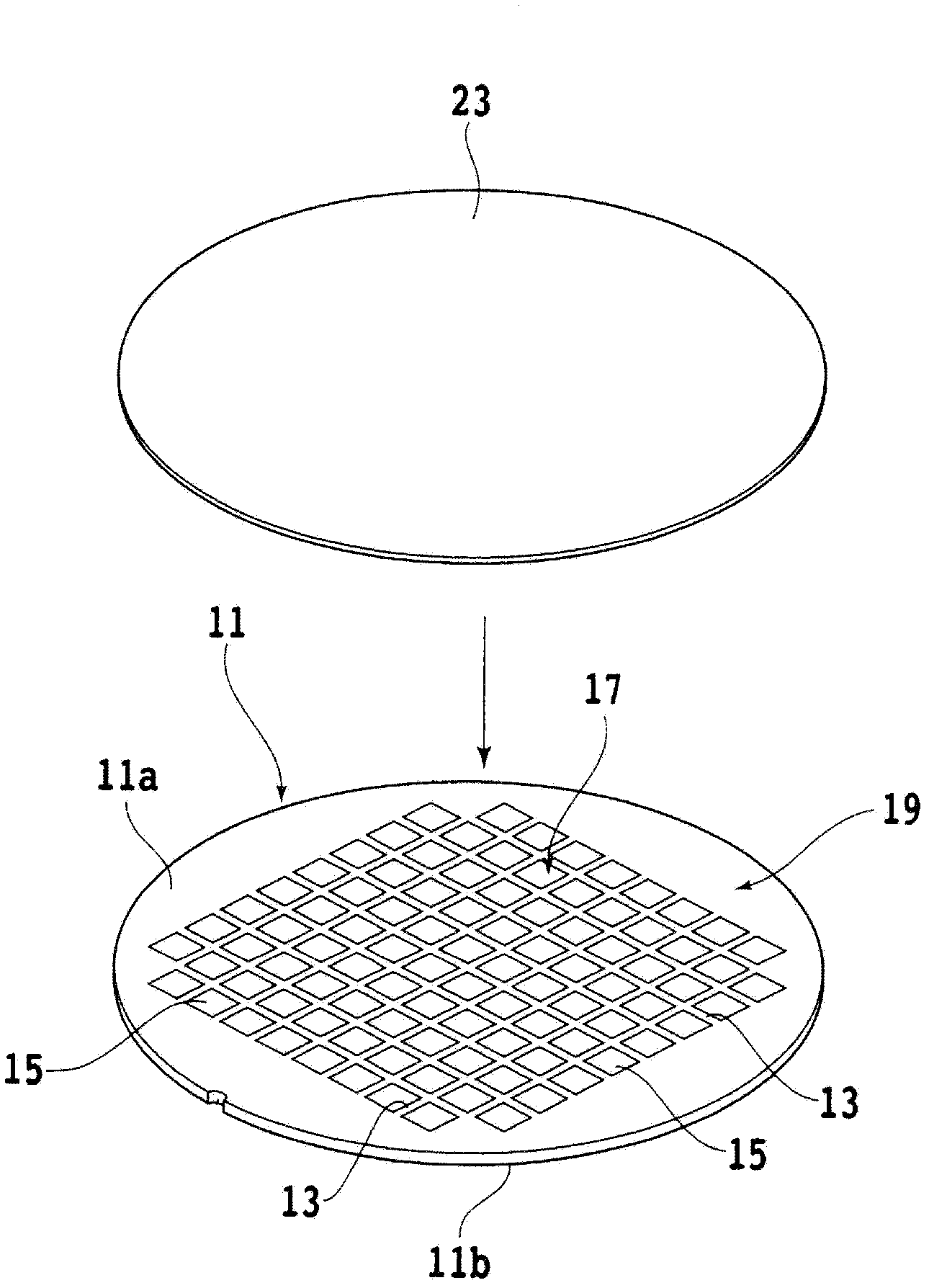
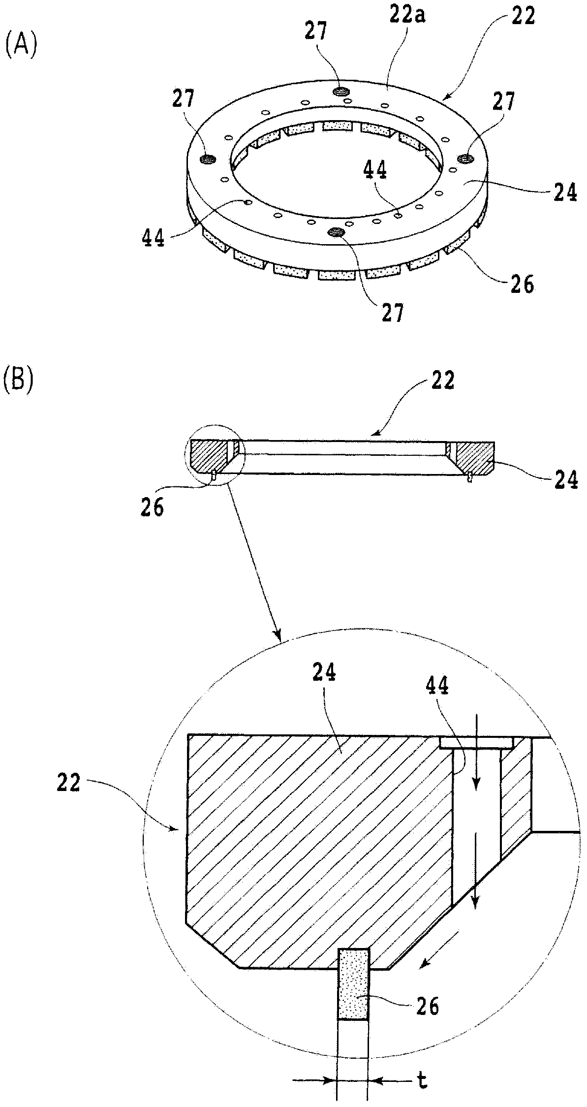
[0050] A plurality of such resin bonded abrasive tools are secured to the free end of the annular base 24 to form a grinding wheel. The grinding wheel was assembled to the wheel base 20, and a sapphire wafer with a thickness of 300 μm was ground under the processing conditions that the spindle speed was 1000 rpm, the chuck table speed was 500 rpm, and the grinding wheel feed rate was 0.2 μm / sec. As a result, the sapphire wafer could be ground to a thickness of 90 μm without pinch and crack.
Embodiment 2
[0052] The metal bond with bronze as the main component is mixed with diamond abrasive grains with a particle size of 5 μm at a volume ratio of 10% to 20%, and HBN particles with a particle size of 1 μm at a volume ratio of 45% to 20%, and shaped into a rectangular parallelepiped shape. It was sintered at a sintering temperature of 700°C for about 1 hour to form a metal bonded abrasive tool.
[0053] A plurality of such metal-bonded abrasive tools are annularly secured to the free end of the annular base 24 to form a grinding wheel. The grinding wheel was mounted on the wheel base 20, and the sapphire wafer was ground under the same processing conditions as in Example 1. As a result, the sapphire wafer could be ground to a thickness of 90 μm without crushing and cracking.
Embodiment 3
[0055] The vitrified bond with silicon dioxide as the main component is mixed with diamond abrasive grains with a particle size of 5 μm at a volume ratio of 10% to 20%, and CBN particles with a particle size of 1 μm at a volume ratio of 45% to 20%, and shaped In the shape of a cuboid. The molded body was sintered at a sintering temperature of 700° C. for about 1 hour to form a vitrified bonded abrasive tool.
[0056] A plurality of such grinding tools are secured to the free end of the annular base 24 to form a grinding wheel. This grinding wheel was fitted to the wheel base 20, and the sapphire wafer was ground under the same conditions as in Example 1. As a result, the sapphire wafer could be ground to a thickness of 90 μm without cracking or cracking.
PUM
| Property | Measurement | Unit |
|---|---|---|
| Particle size | aaaaa | aaaaa |
| Particle size | aaaaa | aaaaa |
| Particle size | aaaaa | aaaaa |
Abstract
Description
Claims
Application Information
 - R&D
- Intellectual Property
- Life Sciences
- Materials
- Tech Scout
- Unparalleled Data Quality
- Higher Quality Content
- 60% Fewer Hallucinations
Browse by: Latest US Patents, China's latest patents, Technical Efficacy Thesaurus, Application Domain, Technology Topic, Popular Technical Reports.
© 2025 PatSnap. All rights reserved.Legal|Privacy policy|Modern Slavery Act Transparency Statement|Sitemap|About US| Contact US: help@patsnap.com


