
Flattened dispersion photonic crystal optical fiber

A photonic crystal fiber, dispersion flattening technology, applied in cladding fiber, optical waveguide light guide, multi-layer core/cladding fiber, etc., can solve the problems of high price and complex system, and achieve the effect of shortening the length

Inactive Publication Date: 2012-04-04
BEIJING UNIV OF POSTS & TELECOMM
View PDF3 Cites 15 Cited by
  • Summary
  • Abstract
  • Description
  • Claims
  • Application Information

AI Technical Summary

Problems solved by technology

Most of the light sources used in the current WDM system are semiconductor lasers with the same number of channels, which are expensive and the system system is complex

Method used


Image

  • Flattened dispersion photonic crystal optical fiber
  • Flattened dispersion photonic crystal optical fiber
  • Flattened dispersion photonic crystal optical fiber

Examples


Embodiment 1

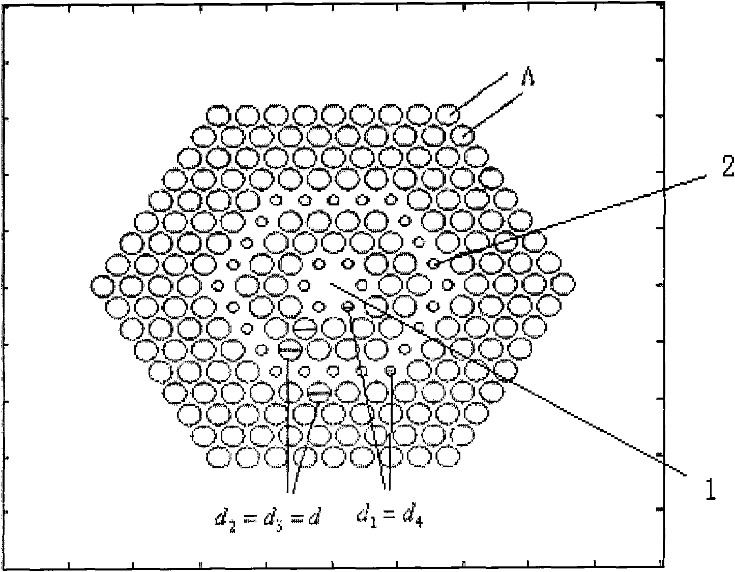
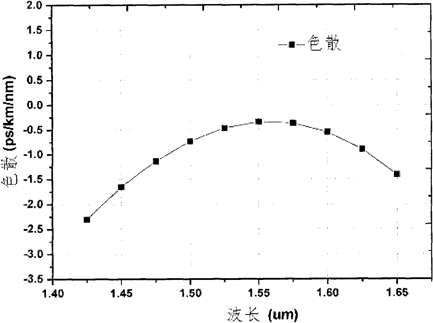
[0032] For quartz materials, photonic crystal fiber structure parameters: Λ = 0.87μm, d 1 / Λ=d 4 / Λ=0.40, the diameter of air holes in other layers satisfies d / Λ=0.82, the corresponding dispersion curve is as follows figure 2 shown. The dispersion curve presents the following characteristics:

[0033] (1) In the wavelength range from 1450nm to 1650nm, the dispersion value of the photonic crystal fiber is in the range of -1.65~-0.335ps / nm / km, and it has the characteristic of flat dispersion;

[0034] (2) Presents a parabolic shape;

[0035] (3) The wavelength corresponding to the maximum dispersion value is 1550nm.

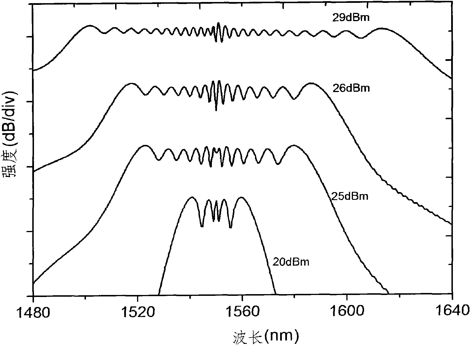
[0036] The nonlinear coefficient at 1550nm wavelength is 33.8W 1 km -1 . When the incident wavelength of the short-pulse laser is 1550nm, the full width at half maximum of the pulse is 1.6ps, and the pump power is 20dBm, 25dBm, 26dBm and 29dBm, the supercontinuum generated after transmission through the 80m-long dispersion-flat photonic crystal fiber, such ...

Embodiment 2

[0038] For quartz materials, photonic crystal fiber structure parameters: Λ = 0.82 μm, d 1 / Λ=d 4 / Λ=0.39, the air hole diameter of other layers satisfies d / Λ=0.81, the corresponding dispersion curve is as follows Figure 4 shown. The dispersion curve presents the following characteristics:

[0039] (1) In the wavelength range of 1400nm to 1600nm, the dispersion value of the photonic crystal fiber is in the range of -11.2~-7.8ps / nm / km, and has the characteristic of flat dispersion;

[0040] (2) Presents a parabolic shape;

[0041] (3) The wavelength corresponding to the maximum dispersion value is 1450nm.

[0042] 40.5W nonlinear coefficient at 1450nm wavelength -1 km -1 .

[0043] The drawing method of the dispersion-flattened photonic crystal fiber of the present invention will be briefly described below.

[0044] The drawing method of the dispersion flattened photonic crystal fiber adopts the existing capillary stacking drawing technology. First, the quartz preform...


PUM

PropertyMeasurementUnit
Dispersion valueaaaaaaaaaa
Nonlinear coefficientaaaaaaaaaa

Abstract

The invention discloses a flattened dispersion photonic crystal optical fiber. A cladding of the optical fiber consists of a plurality of layers of air holes arranged at nodes of a regular hexagon grid, wherein the radius of the first layer of the air holes is d1, the radius of the fourth layer of the air holes is d4, the radius of other layers of the air holes is d, the center distance of adjacent air holes is Lambada, and d is larger than d1 and smaller than Lambada as well as larger than d4 and smaller than Lambada; and a fiber core of the optical fiber is in a double-layer fiber core structure, an inner layer fiber core is a high-refractive-index core zone formed by deletion of the holes at the nodes of the regular hexagon grid, and the outer layer fiber core is a high-refractive-index core zone formed by reducing the diameters of the fourth layer of the air holes. The flattened dispersion photonic crystal optical fiber having high nonlinearity and small normal dispersion value disclosed by the invention can adapt to high-power pulse lasers with different pumping wavelength and can combined with the high-power pulse lasers to compose a wideband flattened super-continuum spectrum light source in 1.55 mum communication waveband.

Description

technical field [0001] The invention relates to the field of optical fiber technology, in particular to a dispersion-flat photonic crystal fiber with high nonlinearity and small normal dispersion value. Background technique [0002] In high-speed, large-capacity optical fiber communication networks, in order to obtain greater communication capacity, the current trend is to combine Wavelength Division Multiplexing (WDM) technology with Optical Time Division Multiplexing (OTDM) technology. Combining, that is, using OTDM technology to improve the single-channel capacity of the WDM system. The key technology of this optical communication method is how to obtain a high repetition rate, multi-wavelength ultrashort optical pulse source. Most of the light sources used in the current WDM system are semiconductor lasers with the same number of channels, which are expensive and the system system is complex. [0003] Photonic crystal fiber [1] , also known as microstructured optical ...

Claims


Application Information

Patent Timeline
IPC IPC(8): G02B6/036G02B6/02
Inventor 张霞任晓敏施雷郑龙王亚苗徐永钊黄永清
Owner BEIJING UNIV OF POSTS & TELECOMM
Learn More