Single-fiber device

A device and single-fiber technology, applied in the field of single-fiber devices, can solve the problems of loss of optical power and receiving sensitivity of optical devices

Inactive Publication Date: 2012-04-04
HUAWEI TECH CO LTD
View PDF7 Cites 5 Cited by
  • Summary
  • Abstract
  • Description
  • Claims
  • Application Information

AI Technical Summary

Problems solved by technology

[0003] However, using a partially transparent and partially reflective filter will lose the transmit optical power and receive sensitivity of the optical device

Method used


Image

  • Single-fiber device
  • Single-fiber device
  • Single-fiber device

Examples


Embodiment 1

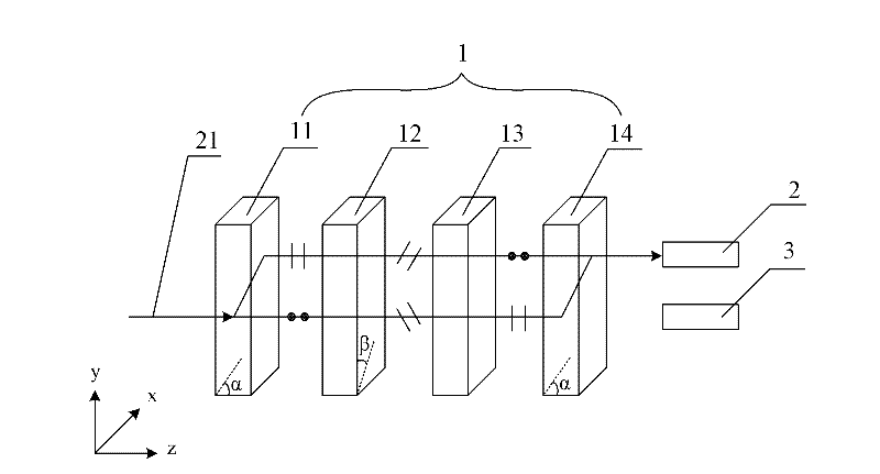
[0024] An embodiment of the present invention provides a single-fiber device, such as figure 2 As shown, it includes a first photodiode 2 (Photo Diode, PD) for receiving incident light 21 and a laser diode 3 (Laser Diode, LD) for emitting outgoing light, and also includes: The same wavelength splitter 1 in the forward direction, including the first birefringent plate 11, the half-wave plate 12, and the 45° Faraday rotation arranged in sequence along the positive direction (ie, the positive direction of the z-axis) and perpendicular to the positive direction (ie, the z-axis) sheet 13 and the same second birefringent sheet 14 as the first birefringent sheet 11; the angle between the optical axis of the first birefringent sheet 11 and the positive direction (ie, the positive direction of the z-axis) is α, 0°<α <90°; the angle between the e-axis of the half-wave plate 12 and the main section of the first birefringent plate 11 (ie, the zy plane) is β, β=67.5° or β=22.5°.

[0025]...

Embodiment 2

[0030] Based on the first embodiment, the embodiment of the present invention provides a single-fiber device, such as Figure 4 As shown, it also includes: a transceiver die 4 (Transistor Outline, TO), which is used to package the first photodiode 2 and the laser diode 3 together. The structure and principle of the same wavelength splitter 1 are the same as those in Embodiment 1, and will not be repeated here. Preferably, the angle α between the optical axis of the first birefringent sheet and the positive direction is α=47.85°, so that the incident light is deviated by a relatively large distance.

[0031] Realize the single-fiber bidirectional device that encapsulates LD and PD in the same TO, and through the above-mentioned same-wavelength splitter, the separation of receiving and transmitting optical paths can be realized. Compared with the existing technology, there is no need to use partial transmission and partial reflection filters. In this way, theoretical lossless t...

Embodiment 3

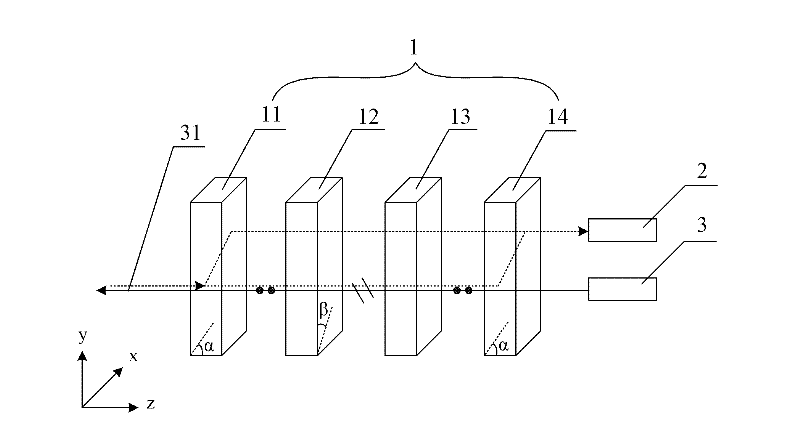
[0033] Based on the first embodiment, the embodiment of the present invention provides a single-fiber device, such as Figure 5 As shown, it also includes: a reflector 5 arranged on the incident light path between the first photodiode 2 and the same-wavelength beam splitter 1, used to reflect the incident light passing through the same-wavelength beam splitter 1, so that the first photodiode 2 Receive incident light; the first receiving die 22 is used to package the first photodiode 2 ; the emitting die 32 is used to package the laser diode 3 . The structure and principle of the same wavelength splitter 1 are the same as those in Embodiment 1, and will not be repeated here.

[0034]The same wavelength single-fiber bidirectional optical device (Bi-Direction Optical Sub-Assembly, BOSA) is realized, and through the above-mentioned same wavelength splitter, the separation of receiving and transmitting optical paths can be realized. Compared with the prior art, there is no need to ...


PUM


Abstract

The invention discloses a single-fiber device and relates to the technical field of optical communication, thereby achieving higher light-emitting power and acceptance sensitivity. The single-fiber device comprises a first photodiode for receiving incident light and a laser diode for emitting emergent light and further comprises a uniform-wavelength optical splitter in a positive direction; the uniform-wavelength optical splitter comprises a first birefringent plate, a half-wave plate, a 45-DEG Faraday rotating plate and a second birefringent plate, which are arranged sequentially along the positive direction and are vertical to the positive direction; the second birefringent plate is the same with the first birefringent plate; an included angle Alpha between the optical axis of the first birefringent plate and the positive direction ranges from 0 zero to 90 DEG; an angle Beta between the e axis of the semi-wave plate and the main cross section of the first birefringent plate is equal to 67.5 DEG or 22.5 DEG; the incident light passes through the uniform-wavelength optical splitter along the positive direction; the emergent light passes through the uniform-wavelength optical splitter along the opposite direction of the positive direction; and the emergent light is linearly polarized light, of which the polarizing direction is vertical to the main cross section of the first birefringent plate.

Description

technical field [0001] The invention relates to the technical field of optical communication, in particular to a single-fiber device. Background technique [0002] At present, in the passive optical network (Passive Optical Network, PON) system, the two-way transmission and reception of the same wavelength single fiber, that is, the separation of the receiving and transmitting optical paths of the same wavelength of light through the same optical fiber is a relatively difficult problem to solve. Existing technologies such as figure 1 As shown, the filter is a partially transmissive and partially reflective filter, so that the light in one direction is directly transmitted through the filter, while the light in the other direction is reflected at the filter, thereby changing the optical path and allowing light of the same wavelength to pass through the filter. The same optical fiber realizes the separation of receiving and transmitting optical paths. [0003] However, using...

Claims


Application Information

Patent Timeline
Patent Type & Authority Applications(China)
IPC IPC(8): G02B6/42
CPCG02B6/42G02B6/4246G02B6/4213G02B6/4215G02B6/27G02B6/272G02B6/2746G02B6/2773G02B6/278G02B6/2793G02B6/4208G02B2006/12116G02F1/09G02F1/095G02F1/0955
Inventor 曾同新张学明李生
Owner HUAWEI TECH CO LTD
Why Eureka
Try Eureka